IDEAD001 Analogue & Digital Electronics
Hello, dear friend, you can consult us at any time if you have any questions, add WeChat: daixieit
IDEAD001 Analogue & Digital Electronics
Coursework 1
Assignment 1
Semester 1
Aim:
The aim of this experiment is to demonstrate the operation of the inverting amplifier and summing amplifier.
Laboratory safety:
• Always check and re-check the circuit wiring before applying power.
• Always switch the circuit power off before changing components or connections. Note also that components might be hot.
• Always ask for directions or help if you are unsure of the correct measurement procedure or circuit connection.
Requirement:
All or some of the following will be required to carry out this task.
• Equipment: signal generator, oscilloscope, dc power supply, prototyping board.
• Components: 741 operational amplifier (or similar), various resistors.
Others
• Jumper wires, cables, NI Multisim or similar circuit simulation software.
Experimental Procedure and Measurement:
Task 1. [15]
The Inverting Amplifier

The voltage output of the inverting amplifier is given by:
Vout = - (Rf / Rin) Vin (1)
Where;
Vout = output voltage,
Vin = input voltage,
Rf = feedback resistor,
Rin = input resistor.
i) Using the formula provided in (1), derive values of Rf and Rin to produce a voltage gain of –100. (Do not use resistor values less than 1k).
ii) Use +12V and –12V to the amplifier voltage supply inputs, but do not switch on the power yet. Illustrate in your logbook how you configure the dc supply to the circuit.
iii) Connect the signal source to the amplifier input. Switch on the power supply and the signal source and adjust the signal source to provide a 50 mV (peak to peak), 1 kHz signal to the amplifier input, Vin. Observe the input and output voltage simultaneously on the oscilloscope and comment on the phase difference. Measure the magnitude of Vout and Vin and compare with expected values.
Task 2. [20]
Measuring the frequency response.
Use the circuit developed in Task 1.
i) Starting from a low frequency, measure the gain of the amplifier and the frequency of the input signal as the frequency of the input signal is increased (up to a maximum of 1 MHz). Plot the frequency response (gain against frequency) of the circuit on log linear graph paper if available. Note particularly the frequency at which the gain of the amplifier starts to reduce. This frequency is the bandwidth of the amplifier in this configuration.
ii) Repeat (i) above for an amplifier with a gain of –10. How does the bandwidth differ from that obtained in (i)?
iii) Determine the gain-bandwidth product for the amplifier circuits tested in i) and ii). Comment on the values obtained.
Task 3. [15]
The Summing Amplifier.
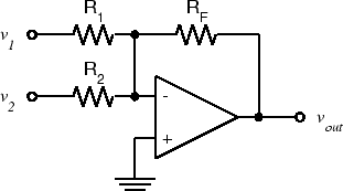
i) Add an additional resistor R2, with a value of twice the value of Rin in task 2 (ii) (i.e., inverting amplifier with gain of 10), to produce the circuit for the summing amplifier as depicted above. The output voltage vout is effectively the sum of the input voltages multiplied by their associated gains. Derive a formula for the summing amplifier depicted above.
ii) Calculate the output voltage for the summing amplifier developed in i) if the same input voltage of 100 mV is applied to both v1 and v2 inputs.
iii) Apply a 100 mV signal to both v1 and v2 inputs of the summing amplifier derived above and measure the output voltage. How does the output voltage compare to the expected value from calculation in ii).
Section B
Technical Report: 1250 words.
(1) Introduction [10]
Use this section to provide background information about the experiment making references to the underpinning principles, which would be key in understanding the results and discussion that follows.
(2) Methodology [10]
The experimental method and procedure, though already provided, should be briefly written in prose here.
(3) Results and Discussion [10]
The results, facts and evidence gathered should be presented and discussed here. This section must provide answers to (or consider) the following questions:
a) Discuss the results obtained in task 1. Consider accuracy and errors. What would happen if the output voltage exceeds the dc power supply voltage?
b) Comment on the bandwidths determined from the two circuits tested. Could the bandwidth for both circuits be estimated from manufacturers data sheets?
c) Compare and discuss the gain-bandwidth product for both circuits.
d) Comment on the results obtained for the summing amplifier. How does the result compare with calculated values?
(4) Conclusion and Recommendation [10]
State what you have learnt and understood following the lab exercise, and any considerations for future experiments.
(5) References [10]
Materials or sources consulted should be listed here.
2023-12-28