Physics 8B Review Problems for Final Exam
Hello, dear friend, you can consult us at any time if you have any questions, add WeChat: daixieit
Review Problems for Final Exam
Physics 8B
Problem 1:
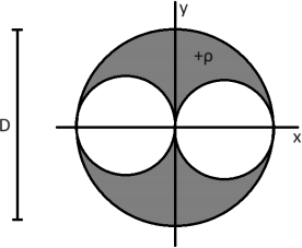
An insulating ball of diameter D and volumetric charge density ρ > 0 is placed at the center of an (x, y)-coordinate system. Two identical spherical regions are carved out from the insulating material as shown in the figure above. The regions that have been carved out are tangent to each other and to the larger insulating ball.
(a) Before the two spherical regions are carved out, determine the magnitude and direction of the electric field produced by the ball everywhere.
(b) After the spherical regions are carved out, determine the magnitude and direction of the electric field produced by the resulting object at an arbitrary point on the x-axis with coordinates (x, 0).
(c) After the spherical regions are carved out, determine the magnitude and direction of the electric field produced by the resulting object at an arbitrary point on the y-axis with coordinates (0, y).
Problem 2:
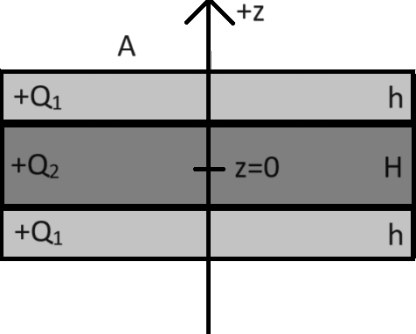
An insulating slab of thickness H and cross-sectional area A is sandwiched between two conducting plates, each with thickness h and cross-sectional area A, as shown in the figure above. The z-axis has its origin in the middle of the insulating slab, and is oriented vertically with the positive direction pointing upward. A net charge Q1 > 0 is placed on both conducting plates, and a charge Q2 > 0 is uniformly distributed throughout the volume of the slab. The system is allowed to come to electrostatic equilibrium. For the purposes of this problem, you may assume that no charges flow across the boundaries between the three regions. You may also assume that the cross-sectional area A of the system is very large and that the two thicknesses h and H are very small in comparison.
(a) What is the volumetric charge density ρ in the thick slab?
(b) What is the electric field produced by the entire system at an arbitrary point on the z-axis with coordinates (0, 0, z)? (Make sure to consider all cases!)
(c) In electrostatic equilibrium, the charges in the conducting plates accumulate on planar surfaces. At which z-coordinate(s) do these planar surfaces form?
(d) For each planar surface in (c), what is the surface charge density that accumulates there?
Problem 3:
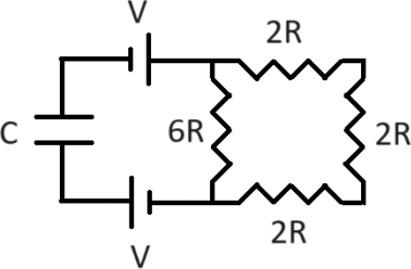
Four resistors, two batteries, and a capacitor are placed in a circuit as shown above. Three of the resistors have resistance 2R, and the fourth resistor has resistance 6R as indicated in the figure. Both batteries have voltage V , and the capacitor has capacitance C. At time t = 0, the capacitor is uncharged.
(a) Determine the equivalent resistance of all four resistors.
(b) What magnitude of charge Q(t) resides on each capacitor plate at time t?
(c) How much current passes through the right-most 2R resistor at time t? (You may find it helpful to use the fact that the current IC(t) through the capacitor satisfies

at all times t.)
(d) At time t, how much total power is being dissipated by all three of the 2R resistors? How does this compare to the total power being dissipated by all four resistors at time t?
Problem 4:
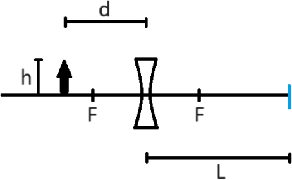
An optical bench contains a diverging lens and an object fixed in place along an optical axis as shown in the figure above. The focal length of the diverging lens has magnitude |f|. The object is located a distance d = 3|f| on the left side of the lens, and has a height h. A small piece of blue tape marks a position located a distance L = 4|f| on the right side of the lens, as shown in the figure.
(a) Perform the ray tracing to determine the qualitative characteristics of the image produced by the object and the diverging lens. Is the image
(i) real or virtual?
(ii) upright or inverted?
(iii) enlarged or reduced?
(b) Now determine the quantitative characteristics of the image. What is the distance between the image and the center of the lens? What is the height of the image? What is its magnification?
Now suppose we wish to make an image appear at the position of the blue marking tape (i.e., at a distance L on the right side of the lens), without moving the components already placed on the bench. Let us consider the prospect of placing an additional lens with focal length magnitude |f| on the bench somewhere between the original lens and the blue marker.
(c) What kind of lens (converging or diverging) is most appropriate to use for this task? Will this ultimately lead to a real or virtual image at the marked position?
(d) At what distance(s) from the original lens does this new lens need to be placed in order to ultimately produce an image at the desired location?
2023-12-22