ENGM029 Power System Analysis Lab Sheet _ Lab 1
Hello, dear friend, you can consult us at any time if you have any questions, add WeChat: daixieit
ENGM029
Power System Analysis
Lab Sheet _ Lab 1
Before your Start
• Ensure you read the instruction document ‘DIgSILENT PowerFactory Modelling Instruction’ and DIgSILENT tutorial documents ‘DIgSILENT Tutorial_Introduction’, ‘DIgSILENT Tutorial_Project’, ‘DIgSILENT Tutorial_LoadFlow’ in the ELE page;
• DIgSILENT PowerFactory provides Student Licence (PF4S); you are encouraged to make direct contact with DIgSILENT to acquire one licence so you can install in your own computer and can access to and practice the simulation study remotely.
Requirements on Report
• A report needs to be produced to answer each question in the lab sheet.
• Assessment: The lab report has a total of 100 marks. The lab report counts for 10% of your final mark.
• The report should be written in a concise manner to both summarising and discussing the results.
• The report should be submitted as PDF file online through ELE2 system by noon, 1st December 2023.
• Avoid any form of plagiarism.
• Format to be used for the results:
|
Voltage in p.u.: |
3 decimal places |
(e.g., 0.965 p.u.) |
|
Voltage in kV: |
1 decimal place |
(e.g., 132.5 kV) |
|
Power in MW/MVA: |
1 decimal place |
(e.g., 200.7 MW) |
1. Objective
The first Power System Analysis lab aims to enhance your knowledge and skills in power system modelling and power flow calculation and analysis. At the end of the lab session, you should be able to build simple power network model, including generator, transformer, transmission line and load, and carry out power flow simulation and analyse by explaining indicative parameters such as active power, reactive power, bus voltage magnitude and phase angle.
2. Introduction
In this Lab Session, you will learn how to simulate a small power transmission network and how to perform power flow calculation in a powerful modern power system simulation software, DIgSILENT PowerFactory. By this simulation exercise, you will learn the underload and overload effects over a long transmission distance on the system operational performance, mitigation method to stablise the bus voltage, and the efficient Newton-Raphson approach and its application in simulation calculation.
3. Problem 1 _ Power Flow Problem [50 marks]
Preparation
Open the project file ‘Power System Analysis_Lab 1_P1.pfd’. Ensure the library contains generator type G1, tower type L6, conductor types 1Z×275 kV_ASCR Zebra 400 mm2 and 4Z×275 kV_ASCR Zebra 400 mm2 (300×300).
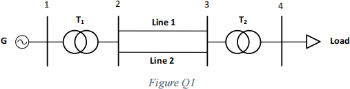
Problem formation:
A load centre is supplied by hydro-generator (11 kV terminal voltage) through a 11/275 kV step-up transformer, a 200 km long double-circuit transmission line operating at 275 kV, and a 275/33 kV step-down transformer. The configuration of the transmission system is given in the Figure Q1. The load level varies from 40 MW to 340 MW.
The parameters of the components are given in the following tables:
Transmission Line

Note: tower, conductor and earth conductor types are included in the library in the project file.
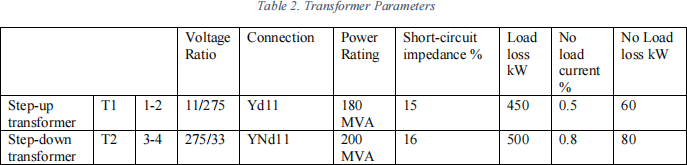
Transformer
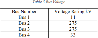
Bus
Generator

Note: generator type is included in the library in the project file
Question 1.1: Network conditions with loads at unity power factor [15 marks]
• Run power flow calculation for loads of 40, 80, 120, 160, 240 and 280 MW
• Record the active and reactive powers as well as voltage magnitudes and phases of
the generator bus and load bus. Present your recordings in the form of table/figure in your report; [10 marks]
• Discuss your findings; [5 marks]
• Note:
o To change the setting of active power for the load, go into the ‘power flow’ tab in the load model;
o To run a power flow calculation, click on the ‘Load Flow Calculation’ button
Question 1.2: Network conditions with loads at 0.9 inductive power factor [15 marks]
• Change the load power factor to 0.9 inductive by introducing appropriate MVAr values
• Run power flow calculation for loads of 40, 80, 120 and 160 MW. And record the
new active and reactive powers as well as voltage magnitudes and phases of the generator bus and load bus. Present your recordings in the form of table/figure in your report; [10 marks]
• Discuss your findings and specify the loads at which the voltage drops below 0.9 p.u.; [5 marks]
• Note:
o To change the setting of reactive power for the load, go into the ‘power flow’ tab in the load model;
Question 1.3: Network conditions with loads at 0.9 inductive power factor with reactive power compensation [20 marks]
• One approach to keep the load voltage as close to 1.0 p.u. as possible is to connect a source of reactive power near the load bus. In this case, a shunt capacitor or a shunt inductor is added to the load bus. It will produce or absorb reactive power to support and maintain the voltage.
• Connect a shunt capacitor/inductor model to the load bus and change its rated voltage and adjust the rated reactive power setting. Repeat the calculations in Question 1.2.
• Find the most suitable values of the reactive power generation/absorption of the shunt capacitor/inductor to maintain the load bus voltage as close as possible to 1.0 p.u. for each load level. And record the reactive power values, new active and reactive powers as well as voltage magnitudes and phases of the generator bus and load bus. Present your recordings in the form of table/figure in your report; [15 marks]
• Discuss your findings; [5 marks]
• Note:
o To set the reactive power rating, goto the ‘shunt RLC’ model, choose capacitor or inductor type, and adjust the rated reactive power value
o Keep the number of step in the ‘shunt capacitor’ as 1.
4. Problem 2 _ N-R Iterative Power Flow Calculation [50 marks]
Preparation
Open the project file ‘Power System Analysis_Lab 1_P2.pfd’. Ensure the library contains generator type G1.
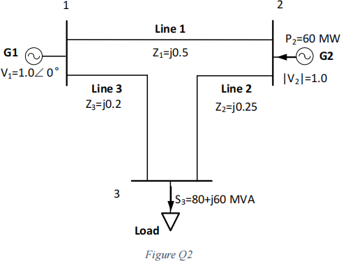
Problem formation:
The three-bus system is given in Figure Q2. System voltage level is 400 kV. Voltages and line impedances are in per unit. The chosen system power base is 100 MVA.
For transmission line, create a ‘line type’ for all three lines. For the ‘line type’:
• Rated voltage: 400 kV
• Rated current: 2 kA
• Type: overheadline
• 1,2- Sequence reactance X’: 10 Ohm/km
• Note: you need to go back to the line model to change the length of line to match the given impedance value in p.u.
For generator, select the provided generator type ‘G1’ in the library. However, change the generator ratings in the type to:
• Rated apparent power: 200 MVA
• Rated voltage: 400 kV
• Rated power factor: 1.0
Question 2.1: Load Flow Result by Simulation [10 marks]
• Run the power flow calculation
• Record the solutions of active and reactive power flows on each branch as well as voltage magnitudes and phases of the buses. Analyse the results and present your recordings in the form of table in your report; [10 marks]
Question 2.2: Verification of Simulation result by Hand Calculation using Newton-Raphson Approach [40 marks]
• Write the bus admittance bus for this system [5 marks]
• Formulate the Newton-Raphson problem and formulate the Jacobian matrix with unknown quantities [5 marks]
• With initial guess of θ2 = θ3 = 0°, |v3| = 1, find the values of Jacobian matrix elements and write the Jacobian matrix J0 [5 marks]
• Find the unknown quantities in the 1st iteration, and compare with the exact results from the simulation [10 marks]
• Continue to the 2nd iteration, finding the updated Jacobian matrix J1 and calculate the unknown quantities in the 2nd iteration, and compare with the exact results from the simulation and provide your remarks. [15 marks]
2023-12-09