COMS10016 | Week 10-11 | Summative Coursework 02: SKETCH CHALLENGE
Hello, dear friend, you can consult us at any time if you have any questions, add WeChat: daixieit
COMS10016 | Week 10-11 | Summative Coursework 02:
SKETCH CHALLENGE
The coursework over approximately the next two weeks counts 30% towards your credit for the COMS10016 unit. The coursework brings together various aspects of the course: file handling, bit manipulation, data structures, dynamic allocation, function pointers, callbacks, and graphics alongside most of the basic C features. You will also get to work on a small multi-module program (though you only have to develop one module called sketch.c).
For this coursework you must work individually. All code you submit must be your own, do not allow others to see your code and do not copy any code parts from peers or other sources. As before, do not paste code snippets or solution details anywhere - this would amount to plagiarism or invite it. The programs we use for checking against the web, your peers and other sources are advanced. Plagiarism may result in 0 marks for the coursework, the entire unit or worse. So just do the right thing an do not attempt to plagiarise, not only due to the serious consequences this has. Remember our lecture in week one re study 101 and have another look at the notes on plagiarism at the top of the unit website again. The assignment is designed to cover approx. 15-20h of work for an average student to achieve an average mark. Do not spend much more than this on the assignment. Instead, ask us for help early if you are stuck either in the 6h of labs that will support this coursework or on Teams in the channel dedicated to this coursework. Again, do not paste code snippets or solution details there or anywhere.
Use only standard libraries, if any, so your code compiles and runs without linking any extra libraries except SDL2. You must use the provided display module only for graphics and make no direct calls to the SDL2 library at all. In contrast to former courseworks, this week's task has three closed-task stages which are each autotested - allowing you to check for yourselves that you secured overall marks of 50%, 58%, and 63%, respectively. Beyond that there will be an open-ended task as usual. Make sure you have finished last week's formative task and all other formative tasks before starting this coursework. Make sure your graphics SDL2 setup works properly as tested last week for the best working environment, however, it is possible to implement a solution to this coursework even without graphics using the testing framework only.
Step 1: Sketch File Formats and Skeleton Code
A Sketch File with the extension (.sk) is a simple binary file that contains a drawing or graphic. There is a basic, intermediate, and advanced version of the file format, each of which is backwards-compatible to include all simpler formats as subsets of the functionality. The formats have been designed to store simple freehand sketches and more complex graphics, even animations in one compact file, in such a way that these can be viewed or replayed as an image or even animation.
Your task will be to develop a program sketch.c which reads in and visualises .sk files using the display module displayfull.h for graphics, a module nearly identical to the one covered in last week's formative exercise. You are not allowed to change the given display module, testing module, nor the function signatures and data structures already provided in the sketch skeleton and header. You are of course allowed to implement functions and add any new function you would like outside the given function signatures and data structures to the sketch.c file. You are given the following files and modules to start your development:
sketch.zip (All Files in one Zip apart from Mac+M1 Makefile)
sketch.h (skeleton header)
sketch.c (skeleton)
Makefile (For Linux and Windows WSL, some old Macs)
IMPORTANT:
For most Macs and M1 Macs compile the sketch viewer and testing suite, respectively, via:
clang -std=c11 -Wall -pedantic -g sketch.c displayfull.c -o sketch -fsanitize=undefined -fsanitize=address `pkg-config --libs --cflags sdl2`
clang -DTESTING -std=c11 -Wall -pedantic -g sketch.c test.c -o test -fsanitize=undefined -fsanitize=address `pkg-config --libs --cflags sdl2`
displayfull.h (display header)
displayfull.c (display module)
test.c (testing framework)
sketch00.sk, sketch01.sk, sketch02.sk, sketch03.sk, sketch04.sk, sketch05.sk, sketch06.sk, sketch07.sk, sketch08.sk, sketch09.sk
As you see, this assignment is going to involve lots of files. It is suggested that you create a new empty folder to work in and extract all files contained in the sketch.zip file into it before you start work. Make sure that the folder permissions are set to owner read only if you work on university computers to make sure nobody else can access your work. Back up your work regularly in any case, since data loss is not a valid extenuating circumstance.
Step 2: Understanding the Basic Sketch File Format
A Basic Sketch File contains a picture made up of white lines drawn on a black background. For simplicity we will stick with a fixed image size of exactly 200x200 pixels for this assignment. Sketch files are encoded as a sequence of single-byte commands, which your program will have to translate into calls to the display module. During drawing a basic sketch file, your program will have to keep track of a current drawing state, which is a data structure defined in sketch.h. This contains the current pixel location (x,y) in the window (which must be initialised as location (0,0) at the beginning of reading a sketch file), a pixel target location (tx,ty) (which must be initialised as (0,0) at the beginning of reading a sketch file), and the currently set tool type (which is initialised as LINE at the beginning of reading a sketch file). The other fields are not used by basic sketch files and should just be initialised to 0. For basic sketch files there are three possible single-byte commands: TOOL to switch active line drawing on or off, DX to move horizontally, and DY to move vertically and draw a line from current to target position if the tool is switched on. Two most significant bits of every command byte determine the opcode (i.e. which of the three commands to do) and the remaining six bits determine the operand (i.e. what data to do it with):
TOOL..If the two most significant bits (or opcode) of a command byte are 1 (most significant bit) and 0, respectively, then the command is interpreted as the TOOL command. This command selects a tool and uses the remaining 6 bits as an unsigned integer operand, which indicates the type of tool. For a Basic Sketch File the tool type can either be NONE = 0 (switching all drawing off) or LINE = 1 (switching line drawing on).
DX....If the two most significant bits of a command byte are both 0 then the command is interpreted as the DX command, that shifts the position of the target location (tx,ty) along the x direction by dx pixels. The operand dx is specified between -32 and 31 encoded as a two-complement integer via the remaining 6 bits of the command byte.
DY....If the two most significant bits of a command byte are 0 (most significant bit) and 1, respectively, then the command is interpreted as the DY opcode, that is shifting the position of the target location (tx,ty) along the y direction by dy pixels. Then, and only if line drawing is switched on, a line is drawn from the current location (x,y) to the target location (tx,ty). Finally, the current location is set to the target location in any case. (If line drawing is switched off then nothing is drawn, but the current location is still changed to the target location). Note that dy is a value between -32 and 31 encoded as a two-complement integer via the remaining 6 bits of the byte.
EXAMPLE FILE: Lets have a look at a very simple sketch file sketch00.sk. Since the .sk files are binary, you can't view them in a text editor like atom easily. You can view the files with the od command in Linux though or use your own HEX viewer developed during formative work last week. To see what the bytes of a sketch file look like use the od command, e.g.:
od -t x1 sketch00.sk
0000000 1e 5e
A number on the first column like 0000000 says what byte position in the binary file the line of output refers to, which is useful for larger files. The rest of the line shows you the bytes in HEX, that is two paired hexadecimal digits for each byte. We can see that the sketch00.sk file contains just two bytes, '1e' and '5e'. Each of these represents a single-byte command. Since each hexadecimal digit represents a four bit nibble, the first byte '1e' translates to binary '0001 1110' and the second byte '5e' translates to binary '0101 1110'. Looking at the two most significant bits (left two bits) tells us which command it is, i.e. which opcode. The first byte starts with '00' and thus is the DX command, the second byte starts with '01' and thus is the DY command.
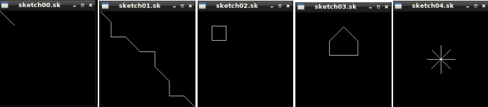
The remaining rightmost six bits represent the operands for each of these commands encoded as two-complement representation, in both cases these are '011110' which represents +30. If needed, review Bits Lecture at this point and remember that the leftmost of the six bits is indicative of the sign. Note that only 6 bits are used to represent the operand, not 8, so only operands between -32 and 31 can be encoded. Thus, the sketch00.sk file has the commands 'DX+30' and 'DY+30'. Given that (x,y) and (tx,ty) are initialised as (0,0) this command will first shift tx to 30, then shift ty to 30 and draw a line from (0,0) to (30,30), and finally set (x,y) to (30,30). The pictures that should be drawn for the five basic sketch files are shown below:

Step 3: Understanding the Skeleton Code
COMPILING, RUNNING AND TESTING YOUR CODE: In order to compile and run the provided skeleton files with graphics use the appropriate Makefile for your system, for instance:
make sketch
After this you can run the program on a sketch file like:
./sketch sketch00.sk
This will at the moment just show an empty 200x200 black display window, since no drawing functionality has been implemented by you yet. You can close the window via the clicking on the 'x' or pressing ESC. Note that on some systems SDL2 may produce memory leaks - we will have to accept this and as long as your program does not leak during testing you will not loose marks for these leaks of course. If you have trouble compiling your code using the make files that means you have not prepared well for the coursework and you machine is still not set up well. Urgently ask us on Teams or in the first lab for help and consider looking at the 'Get you PC Ready' content again re how to compile with SDL2 on your machine.
**ESPECIALLY IMPORTANT SECTION ON TESTING, DO NOT IGNORE**
It is essential that you test your program every time you change your code. If you do not test your program, you cannot know whether it is correct or not. Just as the proof of the pudding is in the eating, the proof of the program is in the testing. Be warned, if you do not test your program, you will almost certainly fail this coursework, simply because your code will be too broken to mark. You can run the tests without even having graphics fully installed by compiling and running the provided skeleton files with 'make', along with the correct Makefile for your system, with this command:
make test
After this you can test your program (which requires all the 10 sketch files for testing to be in your local folder):
./test
We will use exactly the commands in the provided Makefile to test your code (with our fresh test.c copy), so do not change the compilation commands. It cannot be emphasised enough: you must test your code!
**IF YOU IGNORE THIS AND DO NOT TEST YOUR CODE, YOUR CODE WILL ALMOST CERTAINLY BE BROKEN AND YOU WILL FAIL THE COURSEWORK**
Currently testing fails, of course, since you have not implemented functionality. Testing will tell you either which line of tests in the test.c program fails or which drawing command that should be done by a sketch file was not correctly called by your program. (To do that, the testing module 'plays' the role of the graphics module and checks all the graphics calls made against the deterministic sequence of calls that must be made for each of the sketch files. Intercepting, replacing or forwarding calls of a software component is known as a 'proxy'. Note that the compiler flag -DTESTING is critical in conditionally compiling different main functions for use for testing or use with graphics. All the source code of the test file is given to you, so you know exactly how we will test your code.)
STRUCTURE OF THE SKETCH PROGRAM: The sketch.h file summarises the API of the sketch module. If not compiled for TESTING, the main(...) function of sketch.c simply checks that a single argument is provided for the filename and then calls the view(...) function with the provided filename (of the sketch file to view) as argument:
#ifndef TESTING
int main(int n, char *args[n]) {
if (n != 2) { // return usage hint if not exactly one argument
printf("Use ./sketch file\n");
exit(1);
} else view(args[1]); // otherwise view sketch file in argument
return 0;
}
#endif
Exactly like in the excercises last week, in the view(...) function a new display window is created, some state is created and then the run(...) function of the graphics module is called and handed our function processSketch(...) via a function pointer in order to be called back by run(...) repeatedly. Once this run(...) function returns, both state and display are freed:
void view(char *filename) {
display *d = newDisplay(filename, 200, 200);
state *s = newState();
run(d, s, processSketch);
freeState(s);
freeDisplay(d);
}
During the execution of the program our processSketch(...) function is called repeatedly. It will be your task to implement it so that everytime it is called it opens the sketch file, reads the commands and draws the full picture, shows it in the window, and then closes the file. The getName(...) function of the display module can be used to get the filename of the sketch file to open:
bool processSketch(display *d, const char pressedKey, void *data) {
//TO DO: OPEN, PROCESS/DRAW A SKETCH FILE BYTE BY BYTE, THEN CLOSE IT
//NOTE: CHECK DATA HAS BEEN INITIALISED... if (data == NULL) return (pressedKey == 27);
//NOTE: TO GET ACCESS TO THE DRAWING STATE USE... state *s = (state*) data;
//NOTE: TO GET THE FILENAME... char *filename = getName(d);
//NOTE: DO NOT FORGET TO CALL show(d); AND TO RESET THE DRAWING STATE APART FROM
// THE 'START' FIELD AFTER CLOSING THE FILE
return (pressedKey == 27);
}
Finally, to interpret the single-byte commands of a sketch file there are three helper functions which we will focus on first:
// Extract an opcode from a byte (two most significant bits).
int getOpcode(byte b) {...}
// Extract an operand (-32..31) from the rightmost 6 bits of a byte.
int getOperand(byte b) {...}
// Execute the next byte of the command sequence.
void obey(display *d, state *s, byte op) {...}
Step 4: Implementing a Basic Sketch Viewer (overall 50%)
DRAWING STATE: Your first task is to implement the newState(...) and freeState(...) functions. The former should allocate memory for a drawing state structure defined in sketch.h and initialise it as discussed above. The latter function should release this memory.
OPCODES: Your second task is to implement the int getOpcode(byte b) {...} function, which given a single-byte command has to return which of the opcodes DX, DY, or TOOL it represents. The possible opcodes to return for basic commands are defined in the sketch.h header file. Once you have implemented this function correctly the first 10 tests will pass and you should see the output 'Opcode Tests OK.' when testing your program.
OPERANDS: Your third task is to implement the int getOperand(byte b) {...} function, which given a single-byte command has to return the value of the operand represented by the rightmost 6 bits as a two's complement integer. The possible return values range from -32 to 31. When extracting the operand from the byte and storing it in an int remember the sign expansion must be performed correctly (see Bits Lecture for details). Once you have implemented this function correctly the second 10 tests will pass and you should now also see the output 'Operand Tests OK.' when testing your program.
COMMANDS: Your fourth task is to implement the void obey(display *d, state *s, byte op) {...} function. Given pointers to the display and drawing state, and a single-byte command it first has to call the functions to get opcode and operand, and then it has to carry out the command represented. This will mean that you will need to implement each of the three commands. As described above, these may change the drawing state and/or call the line(...) function of the display module. You may want to create a helper function for each of the three commands to keep the obey(...) function small. MAke sure you exactly understand what each command should do by reading the description of basic sketch files again before starting to implement this, every detail matters. Once you have implemented this function correctly and the drawing state is allocated, initialised and realeased correctly then the tests up to test 35 should pass and you should now see another line of success output when testing your program.
READING/VIEWING SKETCH FILES: Your final task in the creation of a basic sketch viewer is to implement the body of the processSketch(...) function. Every time the function is called it should open the sketch file as a binary file, read the command bytes and for each byte read ask the obey(...) function to carry out the command. As said before, the getName(...) function of the display module can be used to get the filename of the sketch file to open. Make sure you call the show(...) function of the display module exactly once after processing the file and obeying the commands in it so that all drawing done can actually be seen in the display window. Also reset the current position, target position and tool of the drawing state back to their initial values either after or before processing your file to comply with the standard. Everytime the processSketch(...) function is called the entire file is processed again. Once you have implemented this function correctly you should see 'ALL BASIC TESTS PASS.' when testing your program. Use the tests in test.c to understand and check the exact call sequences to the display module that your code should produce. You should be able to correctly view the first five example sketch files, that is sketch00.sk to sketch04.sk. If you have reached this point successfully and all basic tests indeed pass successfully then you will have passed your coursework and will receive at least 50 marks. Everybody should work hard to reach at least this point. Before working on the next part of the task backup your work so you can always revert to it.
Step 5: Implementing an Intermediate Sketch Viewer (overall 58%)
One major limitation of the basic sketch file format is that each operand can only be 6bits long. As a consequence it would be difficult to stick to single-byte commands as required for all sketch files and yet provide commands for setting absolute locations for target positions (even when working with 200x200 pixel display windows), or for changing RGBA colour values that are 32bits long. The Intermediate Sketch File Format addresses these problems by starting to use the 'data' field in the drawing state, by extending the TOOL set and by introducing one more command, that is the opcode DATA:
DATA..If the two most significant bits (or opcode) of a command byte are both 1, then the command is interpreted as DATA. This command shifts the bits of the current 'data' field in the drawing state six positions to the left and replaces the six now empty bits with the six (rightmost) operand bits of the command.
In addition, after executing any TOOL command the 'data' field of the drawing state must be set to 0. Together with the DATA command this allows to build up the 'data' value of the drawing state by reading an entire sequence of DATA commands. The Intermediate Sketch File Format also introduces new tool types for using the TOOL command:
First, if the operand of a TOOL command is BLOCK=2 then the 'tool' field of the drawing state is set to BLOCK which indicates that the DY command should draw a filled box with the main diagonal ranging from (x,y) to (tx,ty). Thus, the 'tool' field of the drawing state can now have the values NONE=0, LINE=1, and BLOCK=2. Pay full attention when implementing the behaviour because the block and line functions in the display module have different argument semantics.
Secondly, if the operand of a TOOL command is COLOUR=3 then the 'tool' field is not changed, but the current drawing colour is updated by interpreting the 'data' field of the drawing state as the new unsigned 32bit RGBA integer value. Thus, this is a one-off tool that just changes the drawing colour using a built-up data value.
Thirdly, if the operand of a TOOL command is TARGETX=4 then the 'tool' field is not changed, but the current 'tx' field in the drawing state is updated by interpreting the 'data' field of the drawing state as an absolute location in x direction. Thus, this is a one-off tool that just changes the target x location using a built-up data value.
Fourthly, if the operand of a TOOL command is TARGETY=5 then the 'tool' field is not changed, but the current 'ty' field in the drawing state is updated by interpreting the 'data' field of the drawing state as an absolute location in y direction. Thus, this is a one-off tool that just changes the target y location using a built-up data value.
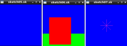
Extend your obey(...) and helper functions to implement the above behaviour. Once you have implemented this functionality correctly you should see 'ALL INTERMEDIATE TESTS PASS.' when testing your program, and you should be able to correctly view the next three example sketch files, that is sketch05.sk to sketch07.sk. Again, use the tests in test.c to understand and check the exact call sequences to the display module that your code should produce. If you have reached this point successfully as described and all intermediate tests indeed pass successfully then you will receive at least 58 marks.
Step 6: Implementing an Advanced Sketch Viewer (overall 63%)
The final advanced version introduces three further tools:
First, if the operand of a TOOL command is SHOW=6 then the 'tool' field of the drawing state is not changed and a single call to the show(...) function of the display module is made immediately.
Secondly, if the operand of a TOOL command is PAUSE=7 then the 'tool' field is not changed, but the pause(...) function of the display module is called immediately using the 'data' field of the drawing state as representing the number of milliseconds to wait. Thus, this is a one-off tool that just causes the system to wait for a bit.
Thirdly, if the operand of a TOOL command is NEXTFRAME=8 then the 'tool' field is not changed, but the current position in the sketch file (i.e. the number of the command starting with 0 for the first command in the file) is stored in the 'start' field and the processing of the file is immediately stopped (for instance by utilising the 'end' field of the drawing state as a sentinel variable that prevents reading the next byte). The so far drawn content is then shown on the display, and the processSketch(...) function returns. Note that the start field is the only field of the state that is not reset after closing the sketch file. It must be used to resume processing with the command following the NEXTFRAME TOOL command once the processSketch(...) function is called again. So instead of processing the sketch file from the start every time processSketch(...) is called, processing is started in the middle of the file as indicated by the start field of the state. This allows to process the content of a sketch file frame-by-frame, animating its content. Use the last two tests in test.c to understand the exact call sequences to the display module that your code should produce.
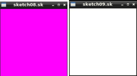
Extend your processSketch(...), obey(...) and helper functions to implement the above behaviour. Once you have implemented this functionality correctly you should see 'ALL ADVANCED TESTS PASS.' when testing your program. Tests are deliberately kept simple to focus on key functionality only. You should be able to correctly view all example sketch files, that is sketch00.sk to sketch09.sk. If you have reached this point successfully as described and all tests indeed pass successfully then you will receive at least 63 marks.
Step 7: Open-ended Task
Only if you have time left, and you have fully finished all closed tasks and if you are interested, you can do some extra open-ended work in your own program called converter.c on the following task: Using only standard libraries as before and the exact given displayfull.h module for graphics (no other calls to SDL2 are allowed and compilation must be straight forward via clang -std=c11 -Wall -pedantic -g converter.c displayfull.c -I/usr/include/SDL2 -lSDL2 -lm -o converter -fsanitize=undefined -fsanitize=address on MVB2.11 Lab machines), write a program that takes a PGM image file in the basic format (see pgm.c from the lectures) and converts and outputs it into a sketch file fully compliant with the description in the closed task:
./converter myimage.pgm
File myimage.sk has been written.
The resulting sketch file should be as small as possible and show the exact same image when viewed with the sketch viewer. In a second step, and only if you have time, extend your converter so that if your converter is called with this sketch file it produces the exact PGM image file that was used to create the sketch file in the first place (lossless):
./converter myimage.sk
File myimage.pgm has been written.
Remember you can only use the displayfull.h module, NOT ANY other SDL2 functionality (like reading pixel values). Test your program and make sure it works on at least the two images bands.pgm and fractal.pgm. A jpg approximation of the two images is shown below:

Write the source file converter.c which must compile error-free and warning-free for your submission, and your testing of your program (if called with no arguments) should convince us that your functionality is fully correct. There should be no segfaults or memory leaks from your own code. Rather submit something simple that works robustly and error-free than buggy code (which may earn you very very few marks only, we will be much stricter this time regarding bugs). You must also write a summary file readme.txt which describes your aims for the program and how far you got with it in strictly no more than 100 words. You must start your summary by telling us the file size of the lossless sketch file your converter creates from fractal.pgm. There are no marks for report writing, but the summary may be necessary for us to make sense of the program. Even if your program is very basic and runs fine, still submit it: just treating every pixel of the PGM image as producing a COLOUR, TARGETX, TARGETY, and DY command (together with the DATA commands for loading the data) to draw a BLOCK in the sketch file can solve the first part of the above task in a basic way (although such a sketch file will be large). Whenever you have reached a well working version, take a copy of your work, so you can revert back to it at any point. For extended work you may want to do some research into techniques such as RunLength Encoding (RLE) in one or more dimensions to make your sketch files as small as possible. The task is truly open-ended, so make absolutely sure you do not overspend on time. Make sure your programming adheres to the unit style guide and you test all functions that are not just reading or writing to the file systems, isolate the latter in your program to be able to test the rest properly. Enjoy programming, our lab team and Teams are there for you if you need advise!
A mark out of 37 for the extra work will be awarded by swiftly reading the summary, checking whether your program matches what you claim, judging the sophistication and extent of what has been done, and checking whether the program follows the conventions and advice in the lectures and style guide. In particular, writing tests as part of the program is very important and fundamental for first class work. Also recommended is working in very small steps, one step/self-developed test at a time, keeping your program in a working state. Again, make sure you do manage your time well and stop at a reasonable point. Remember, there are significantly deminishing returns.
The overall mark will aim to make your total for the assignment meet the university marking scale. So assuming you get full 63 marks for the sketch.c program, for the open-ended task 5/37 means "this raises your total result from very good to almost excellent", 7/37 onwards means "this raises your total result to excellent, overall above and beyond what was expected", 12/37 means "brilliant work", 17/37 means "truly exceptional work, potential mastery of the subject area" and 27/37 means "novel and publishable in a research journal".
Step 8: Submit
Submit your work via the SKETCH submission point on Blackboard for the unit. You are responsible for early submission, thus submit AT LEAST an hour before the deadline (deadline is 01:00pm UK time on 13 Dec 2023) to make sure there are no upload problems. The university systems will automatically apply penalties even if it is late by only one second. You must submit ALL files as attachements in a SINGLE submission. If you decide to resubmit you MUST submit ALL FILES AGAIN - only the files in your last submission will be marked. If your last submission is late you will receive the associated penalty in any case.
Closed Task: Submit your program sketch.c as one attached file (not Sketch.c or any other name, unless you want to lose marks, and not the compiled program, not any zip file etc). Make sure your program compiles without warnings, without using any additional libraries, runs without errors, and doesn't still contain debugging print statements. All code you submit must be your own, do not copy any code parts from peers or other sources and make sure only you have ever had access to your own code. The programs we use for checking against the web and your peers are advanced. Plagiarism may result in 0 marks for the coursework, the entire unit, or worse. Note that our plagiarism checks will be significantly more involved this time since code is more complex than on the last assignment.
Open-ended Task: If you attempted the open-ended part, then also submit as attachements your extra program converter.c and a readme.txt file with any comments you might want to make. So in this case you will submit exactly three files with the names as discussed above. Again, make sure your programs compile without warnings, and run without errors.
2023-12-07