CS1010S: Programming Methodology Mission 2
Hello, dear friend, you can consult us at any time if you have any questions, add WeChat: daixieit
CS1010S: Programming Methodology
Semester I, 2021/2022
Mission 2
Cyclic Runes
Required Files
● mission02-template.py
● runes.py
● graphics.py
● PyGif.py
Background
After passing through the two doors in your previous mission, you arrive in a large spacious hall with no visible exits except for a large hole in the ceiling, from which a bright beam of light illuminates the entire hall. In one corner, you find two raised terminals with an interface similar to the empty spaces you found on the doors. You can barely see the first letters on their interfaces - R and I.
This mission has two tasks.
Task 1a: Fractal (5 marks)
On the terminals, you see the symbols glow - reminiscent of the previous rooms. Yet they represented all the complexities that came before them in simple elegant patterns. It will be well for you to comprehend the similarities and differences.
Write a function fractal that takes as arguments a rune and an integer n > 0. It should generate the rune below by means of a recursive process with the following command:
show ( fractal ( make_cross ( rcross_bb ) , 3))
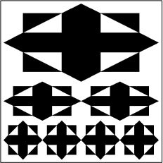
To determine that your function is correct for n > 3, check that the same command with n = 7 draws:
You should check that your function will perform correctly for any arbitary number of draws that is 1 or above.
Task 1b: Fractal - Iteration (5 marks)
Write a function fractal_iter that takes in the same arguments as fractal but it will generate the output in an iterative way this time.
The function should generate the same rune as the recursive one by replacing fractal with fractal_iter in your test functions.
Task 1c: Dual Fractals (5 marks)
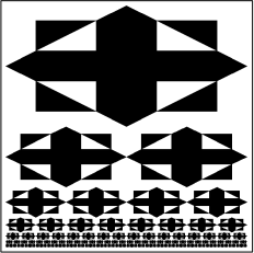
Write a function dual_fractal that takes as arguments 2 runes and an integer n > 0. It should generate the rune below by means of a recursive process with the following command:
show ( dual_fractal ( make_cross ( rcross_bb ) , make_cross ( nova_bb ) , 4))
The first rune is used for every odd layer in the fractal starting from the largest rune, whereas the second rune is used for every even layer in the fractal.
You should check that your function will perform correctly for any arbitary number of draws that is 1 or above.
Task 1d: Dual Fractals - Iteration (5 marks)
Write a function dual_fractal_iter that takes in the same arguments as dual_fractal but it will generate the output in an iterative way.
The function should generate the same rune as the recursive one by replacing dual_fractal with dual_fractal_iter in your test functions.
Note: In the template file all functions are defined as some_function(params). It doesn’t mean that all functions take in only one parameter. It’s your job to figure out what parameters each function should take and replace params accordingly.
Task 2: 3D Runes (10 marks)
For the second task, you are expected to think spatially and show acute sense of perception. This will prove that you are able to look at problems from different angles and choose the appropriate line of attack.
Note: Before you start on this task, you may want to read the background reading (see Appendix).
Runes can be used as representations of 3D scenes. Instead of simple flat runes, the runes can possess surface components of varying depth – also known as depth maps. In this task, darker areas are closer to you while lighter areas are further away. The following diagram illustrates how such runes – or depth maps – are interpreted. You can imagine the nova_bb as a pattern floating on the background:
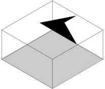
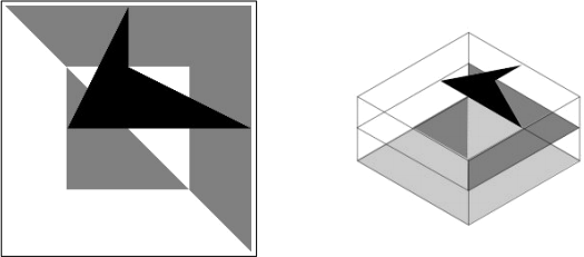
Now, observe a slightly more complicated depth map and its isometric projection. The following depth map shows the nova_bb rune in black (darker) and hence is closer to you than the rcross_bb rune in light grey.
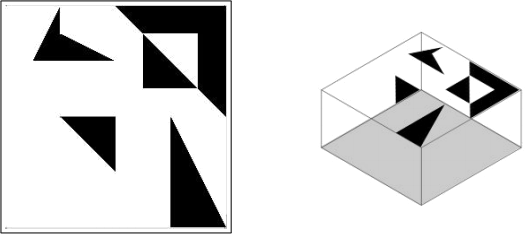
The next one shows the isometric projection of the mosaic rune from Mission 1.
Now that you are familiar with interpreting runes as depth maps, try generating your first stereogram, anaglyph or hollusion. Here, a stereogram refers to a Single Image Random Dot Stereogram (SIRDS) - an image that possesses 3D information that allows you to view the 3D object by use of the wall-eyed vision technique (http://en.wikipedia.org/wiki/Autostereogram#Viewingtechniques). On the other hand, if you have difficulty viewing autostereograms, anaglyphs would be an easier option. Anaglyphs provide 3D stereo-scopic view of 3D objects with the use of coloured lenses. In our case, you should use a Red-Cyan anaglyph glass (http://en.wikipedia.org/wiki/Anaglyph_3D). Alternatively, you may try using a hollusion, which is an implementation of wiggle stereoscopy, as a simple way of viewing stereograms.
Use the command stereogram, anaglyph or hollusion instead of show to generate stereo-grams or anaglyphs instead of depth maps. For example, to generate the stereogram for nova_bb, we can use the following command:
stereogram ( nova_bb )
You can then start practicing with the runes you generated previously and convert them to stereograms or anaglyphs. Just remember to use stereogram(...), anaglyph(...) or hollusion(...) instead of show(...). Now is a good time to take a break and enjoy viewing your wonderful creations.
Creating Overlays
It’s nice to be able to generate and view stereograms or anaglyphs, but knowing how to interpret depth maps is not enough to do this exercise. We shall now introduce several more transformation primitives that we have written for your usage. They are: overlay, overlay_frac, scale, scale_independent, and translate.
The combinators overlay and overlay_frac will help you create depth maps easily. These functions overlay two painters, one on top of the other. With overlay, each painter will occupy half of the depth range of the resulting depth map. Figure 2 provides two examples of depth maps produced by overlaying two painters.
To make things more interesting, consider the possibilities should you nest the overlay command. It works analogously to the stack command introduced in the lecture. overlay
squeezes the original depth range occupied by each of the runes by half. For example, doing this:
overlay(overlay(nova_bb, heart_bb), rcross_bb)will result in the creation of the following depth map:
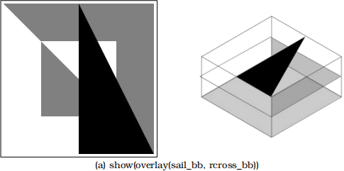
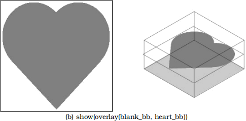
Figure 2: Examples of depth maps laid out using overlay command. Note that the depth space is divided equally between the two runes. In (b), notice that the first rune (occupying the top-most layer) is a blank rune blank_bb.
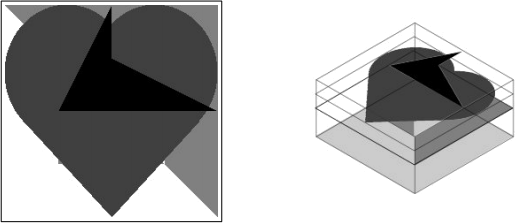
(Hint: use show(overlay(overlay(nova_bb, heart_bb), rcross_bb)) to display it.)
The first rune, which is an overlay of nova_bb and heart_bb, is squeezed by half and occupies the top half of the depth range. The second rune, rcross_bb, occupies the bottom half.
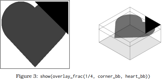
The combinator overlay_frac performs similarly to overlay. However, we may also specify the fraction of the total depth range occupied by each rune. This parameter determines the fraction of the depth range occupied by the first rune; the remainder of the depth range will be occupied by the second rune. In the following example, corner_bb takes up the top 1/4 of the depth range, while heart_bb occupies the remainder 3/4. (These two combinators are so similar that we actually implement one in terms of the other. Can you guess which one is implemented in terms of which?)
Your Task
Displayed prominently on the wall beside the terminal are the basic runes and a complex 3D rune of which you are expected to conjure.
Write a function steps that takes four runes as arguments and arranges them in a 2 × 2 square, starting with the top-right corner, going clockwise, just like mosaic in Mission 1. However, the four runes are now placed at different depths as shown in the following example:
steps(rcross_bb, sail_bb, corner_bb, nova_bb)will result in the following depth map.
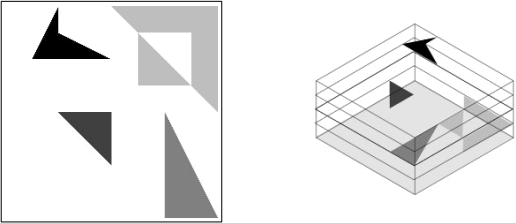
Note that the rcross_bb is at the lowest level (lightest shade of grey) and nova_bb is at the highest level (black). Also, note that the four runes are spaced equally apart along the z-axis. Hint: You may want to make use of the blank painter blank_bb and/or reuse a function that you have defined previously.
Appendix: Background Reading on Stereograms
Here we provide some background information on how stereograms work and how they are generated. This material is purely for your reading pleasure. You do not have to understand how stereograms are generated to complete the mission. Read on if you’re interested!
First, we need to understand how our eyes work to give us stereo vision. We are able to see depth because we have two eyes that are spaced a distance apart. When we look at an object, both eyes will converge on the object. However, due to the horizontal separation, each eye will see a slightly different perspective of the object. This is known as horizontal disparity. Our brains have developed an ability to fuse images from both eyes together so that we don’t see doubles (known as stereopsis). This disparity also allows our brain to infer depth.
The earliest stereograms were made from a pair of photographs, specially taken so that each of them captures a slight horizontal disparity. Stereoscopes were devices that present the correct image from these photographs to each eye using mirrors or prisms.
Anaglyph images are another popular stereogram technology. You may have seen such images in comic books or 3D movies. The image meant for the left eye is printed in red while the image meant for the right eye is superimposed over the red image using cyan. Anaglyph images look to the naked eye quite like what you will see when you experience double-vision. However, special “anaglyph glasses” which filter red images to one eye and cyan images to the other can be used to provide the appropriate image to each eye.
Figure 4 is an example of an anaglyph; keep your 3D anaglyph glasses within reach!
The stereograms that we are more interested about are the same ones popularized by the “Magic Eye” series of books which have fascinated many (Have you seen them?). These stereograms are known as autostereograms or Single Image Stereograms (SIS) because all of the depth information in the stereogram is contained within one image, in contrast to the pairs of images (stereo pairs) used by earlier methods. Figure 8 at the end of this appendix shows a sample autostereogram. These are the same kind of stereograms generated in this mission. (If you can’t see the stereogram, the next section will help you with that.)
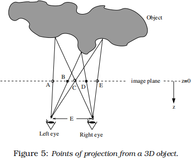
So, how do autostereograms work? We treat the stereogram as points of projection from the 3D object onto an image plane situated between the object and the eyes, as shown in Figure 5. Since points A and C are projected from the same point on the object (to different eyes), they should have the same colour. Similarly, points B and D should have the same colour too. Note that by the same reasoning, point E must have the same colour as point C and thus, A, C, and E must have the same colour. If we continue this process for the whole image plane, we eventually get groups of points that are constrained to have the same colour. We can then either allocate colours randomly (and get a stereogram similar to that in Figure 8) or allocate colours that show some pattern or image.
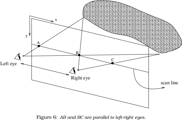
An important note that applies to all stereogram generation methods is that we need only work with one scan line at a time. A scan line is a line on the image plane that is horizontal with respect to the two eyes (Figure 6). This is because all pairs of projected points (from the same point on the object) form line segments that are parallel to LR, the line segment between the two eyes.
Let’s dive into the more technical aspects. As this is a 3-D modeling, we need coordinates x, y and z. Let x run horizontally from the left eye to the right eye and y run vertically
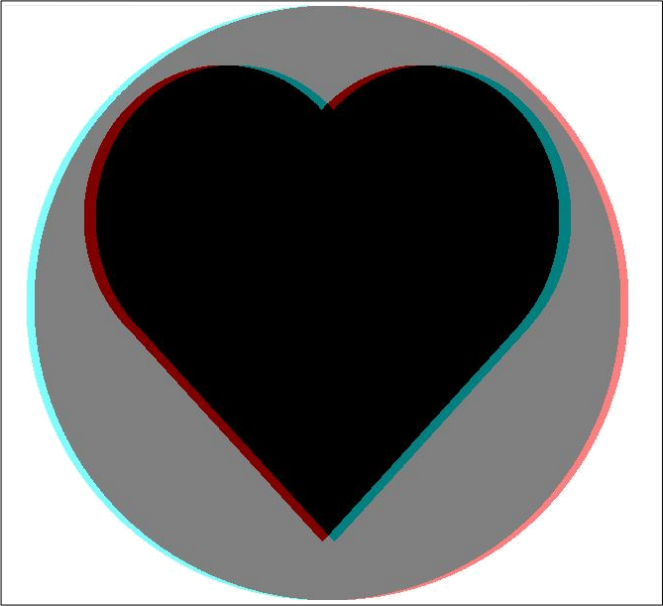
Figure 4: A sample anaglyph. When viewed with Red Cyan 3D anaglyph glasses, you will see a heart floating above a circle.
downwards. Both x and y are parallel to the image plane (Figure 6). z runs perpendicularly to the image plane. It is zero on the image plane, positive between the eyes and the image plane, and negative behind the image plane.
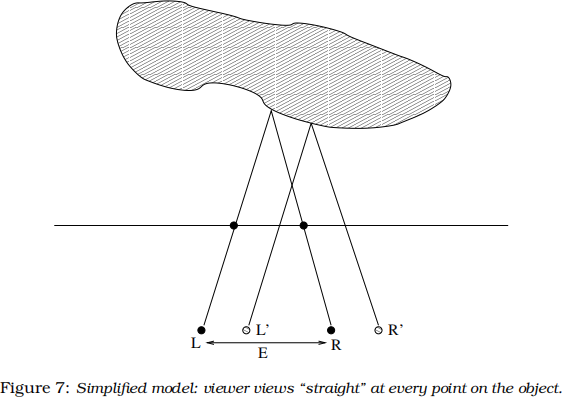
We can introduce a major simplification to this model. We shall assume that the eyes look “straight” at every point in the stereogram (Figure 7). The rationale is that the viewer may not have any preference for viewing positions, hence we shall choose one that is most reasonable. This model also comes in handy when doing visibility tracing.
By similar triangles, separation of two points constrained to be the same colour,
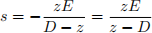
This separation s is called the stereo separation, and it is an important value that we will use in all stereogram generation algorithms.
Given the value z of a particular point on a 3D object, we can calculate the stereo separation and find the two points which must be constrained to having the same colour on the stereogram image (Figure 7). Now, a 3D object can be described by a function f(x, y) that returns the z value at point (x, y). This function is sometimes referred to as z-function. Similarly, a 2D greyscale image can be used as a graphical representation of a z-function. Such images are known as depth maps. The lightness or darkness of each point on the depth map represents its depth in 3D. In the mission, we learn that quilts can be interpreted as depth maps.
The basic theory behind stereogram creation is very simple, it is a problem of finding groups of points which are constrained to have the same colour. In our algorithm, we simply allocate random colours to each group of constrained points, thus earning it the name: Single Image Random Dot Stereograms (SIRDS).
How to view stereograms
Two mechanisms are in play to help us see the world around us: first, our eyes roll inwards towards each other so that each eye points towards the same object (convergence); second, our eyes’ lenses adjust to get a clear image (focus). The trick to viewing stereograms lies in decoupling these two mechanisms so that our eyes converge at a point behind the stereogram picture. The eyes should be looking almost in parallel at the picture, but at the same time focused on the picture. This way of viewing stereograms is known as wall-eyed viewing.
One way to view stereograms is to imagine that you are looking at an object some distance behind the stereogram. It feels somewhat like looking at your reflection in the mirror. When you are looking at your reflection, your eyes actually converge at a point behind the glass pane. If you switched between looking at the glass pane itself to looking at your reflection, then you should have gotten a sense of how it feels like to look at an object behind the stereogram. If you can do this, you will see double after some time because your eyes are looking at different places in the picture. Hopefully your brain will put two and two together and voilà! you will see a beautiful 3D object.
Another popular way to view stereograms is to bring the picture close to your face. It’s
best to bury your nose into the picture. At such a close distance, your eyes give up on trying to converge upon an object and roll back into wall-eyed viewing positions, just like if you were looking at an object extremely far away. Now, slowly pull the picture away from your face, or your face away from the picture, but keep the same relaxed sensation in your eyes so that you see double. At some point, you will see your stereogram.
It is not natural for us to view stereograms because decoupling focus from convergence goes against our instincts and serves no useful purpose in daily life. Early humans could ill afford to decouple convergence from focus by mistake just when they were chasing their dinner or running away from a lion!
However, it is not that hard to view stereograms too—it just takes a little bit of practice, like learning how to swim or how a ride a bicycle. Remember to try easy, not hard; viewing stereograms does not involve straining your eyes. Don’t worry if it does not come to you naturally—you do not need to be able to view stereograms to do the mission.
Now, try to view the sample stereogram in Figure 8!
2021-09-27