EEEN60481 Coursework Performance Evaluation of Wireless Communication Systems
Hello, dear friend, you can consult us at any time if you have any questions, add WeChat: daixieit
EEEN60481 Coursework
Performance Evaluation of Wireless Communication Systems
Using Monte-Carlo Simulations
October 2023
1 Performance of a Basic Wireless Communication System Using Monte-Carlo Simulations
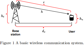
As shown in Figure 1, let’s consider a wireless communication system, where the transmitter (base station) conveys information, x, with a transmit power of Pt to the receiver (user). Let’s assume that the transmitter is located r meters away from the receiver, where the horizontal distance between the transmitter and receiver is dx meters, the height of the transmitter is ht meters, and the height of the receiver is hu meters.
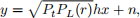
The received signal at the receiver is expressed as
 (1)
(1)
where his the small-scale fading channel which is assumed to be a complex Gaussian random variable, x is the transmit signal with unit energy, and n ∼ CⅥ(0, N0 ) is the additive white Gaussian noise (AWGN) with mean zero and variance of N0. Furthermore, PL (r) is the free space path-loss expressed as
 (2)
(2)
where Gt is the transmit antenna gain, Gr is the receive antenna gain, λ = c/f is the wavelength, c is the speed of light and f is the operating frequency of the system.
Using (1), the received signal-to-noise ratio (SNR) is expressed as
 (3)
(3)
where 
Using (3), the ergodic capacity of the system is expressed as

where E[.] represents the expectation operator.
![]() Furthermore, the probability when the SNR is below or equal to a certain threshold, γth , is termed as outage probability. Therefore, using (3), it is expressed as
Furthermore, the probability when the SNR is below or equal to a certain threshold, γth , is termed as outage probability. Therefore, using (3), it is expressed as
 (5)
(5)
Task 1 (60 Marks): Use the Monte-Carlo simulations with 106 realizationstoplot the ergodic capacity and outage probability of the system against γt = [20 : 60] dB with the following parameters.
. ht = 10 m, hu = 6 m, dx = 80 m, Gt = Gr = 20 dBi, f = 900 MHz, and γth = 4 dB. Furthermore, h ∼ CN(µ, 1), when µ = 0, the channel amplitude, |h|, follow Rayleigh distribution, and when  |h| is assumed to follow Rician distribution with a Rician factor of K = 8 dB.
. The distribution of |h| should be appropriately chosen for the following two scenarios. 1)- There is a line-of-sight (LOS) between the transmitter and receiver.
2)- The direct LOS link between the transmitter and receiver has been blocked.
2 Performance of Intelligent Reflecting Surface (IRS)-assisted Wire- less Communication Systems
Intelligent reflecting surface (IRS) is a new technology which significantly improves the performance of wireless communication systems. An IRS consists of a number of nearly passive reflecting elements, and it is used to form strong beams and reflect the incident signals to a desired direction by intelligently manipulating the phase of each reflecting element [1].
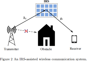
As shown in Figure 2, let’s consider a single-input single-output (SISO) wireless communication sys- tem, where the direct link between the transmitter (T) and receiver (R) has been blocked. However, the communication is established through an IRS equipped with N reflecting elements. It is assumed that by exploiting the IRS, T transmits the signal x to R. Since the direct T-R link is not available, the transmitted signal first arrives at the IRS through the fading channels, hi ∀i = 1,...,N. The IRS reflecting elements then apply phase shifts, θi ∈ [0, 2π), to form strong beams and reflect the incident signal to R through the fading channels, gi ∀i = 1,...,N. The fading channel coefficients are assumed to be mutually independent and identically distributed complex Gaussian random variables, which can
be expressed as hi ∼ CN(µh ,σh(2)) and gi ∼ CN(µg ,σg(2)), where {µh ,µg } and {σh(2),σg(2)} are the mean and
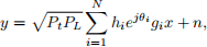
variances, respectively. Therefore, the received signal at R is expressed as
 (6)
(6)
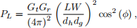
where Pt is the transmit power, x is the transmit signal with unit energy, and n ∼ CN(0, N0 ) is the additive white Gaussian noise (AWGN). Furthermore, PL is the large-scale path-loss expressed as [2]
 (7)
(7)
where Gt is the transmit antenna gain, Gr is the receive antenna gain, L and W are the length and width of the IRS, dh is the T-IRS distance, dg is the IRS-R distance, and ϕ is the angle of incidence.
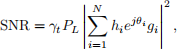
Using (6), the received SNR is expressed as
 (8)
(8)
where 
2.1 IRS with Optimal Phase Shifts
Let’s express the IRS fading channels in terms of their respective amplitudes and phases as hi = |hi |exp(−jarg (hi )) and gi = |gi |exp(−jarg (gi )), where {|hi | , |gi |} and {arg (hi ) , arg (gi )} are the am- plitudes and phases, respectively. Moreover, it is assumed that perfect channel state information (CSI) is available at the IRS, which implies that the phases of the IRS fading channels are perfectly known at the IRS. Additionally, the IRS is assumed to have the capability to apply continuous phase shifts within the entire interval of θi ∈ [0, 2π). Therefore, in order to maximize the received SNR, the IRS applies phase shifts to align the phases of hi and gi , which leads to an optimal phase shift model, i.e. θi = arg (hi ) + arg (gi ). As a result, the received SNR given in (8) takes the following form.
 (9)
(9)
where |hi | and |gi | are the channel amplitudes for the T-IRS and IRS-R fading channels, respectively.
For further information on IRS technology, please refer to the provided references (i.e., [1] and [2]).
Task 2 (40 Marks): Use the Monte-Carlo simulations with 106 realizationstoplot the ergodic capacity and outage probability of the system against γt = [10 : 40] dB with the following parameters.
. N = {25, 50, 100}, Gt = Gr = 10 dBi, L = W = 2 m, dh = dg = 25 m, ϕ = 30o , and γth = 10 dB. Moreover, the IRS fading channel coefficients are assumed to be zero-mean complex Gaussian random variables , i.e. hi ∼ CN(0, 1) and gi ∼ CN(0, 1).
3 Report Structure
Each student is required to submit a report that contains
1. A cover page containing the student’s full name, ID and the title of the coursework.
2. A table of content.
3. An introduction to Monte Carlo simulations.
4. Results and Discussion: All figures should be clearly visible with captions, labels and legends. Each figure must be analysed and discussed.
5. A conclusion and outcome of the coursework.
6. List of references.
7. Matlab code with comments for each line. Please note, screenshot is not permitted !
[1] S. Gong, X. Lu, D. T. Hoang, D. Niyato, L. Shu, D. I. Kim, and Y.-C. Liang, “Toward smart wireless communications via intelligent reflecting surfaces: A contemporary survey,” IEEE Communications Surveys & Tutorials, vol. 22, no. 4, pp. 2283–2314, 2020.
[2] O. Ozdogan, E. Björnson, and E. G. Larsson, “Intelligent reflecting surfaces: Physics, propagation,
and pathloss modeling,” IEEE Wireless Communications Letters, vol. 9, no. 5, pp. 581–585, 2020.
2023-11-02