ELEC9711 Assignment 2
Hello, dear friend, you can consult us at any time if you have any questions, add WeChat: daixieit
ELEC9711 Assignment 2- due Friday, week 6, 3pm
For the resonant ZVS DC-DC converter of Figure 1, the inductor L and capacitor C are sufficiently large so that current and voltage maybe considered to remain constant during a switching period respectively.
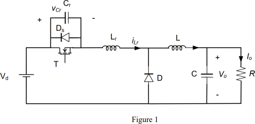
The following parameters are given:
Vd = 20 V , Lr = 1.5 μH , Cr = 0.05 μF , Vo = 11 V , and Io = 4 A .
(a) Please calculate out the required switching frequency for the above design. [2 marks]
(b) Sketch the waveforms for iLr and vCr with respect to the switch status and clearly describe the resonant process. With the aid of your waveforms, show why the resonant circuit can help lower the loss in the switch. [3 marks]
(c) Can we use the same Lr and Cr values for a ZCS converter design to operate with the given input and output V&I ratings? If yes, what is the required switching frequency? If not, please explain why it won’t work and find a new value for Cr that could fix the problem (same V/I/fs values). [Typically, you should sketch the waveforms for iLr and vCr with respect to the switch status and time to explain this.] [3 marks]
(d) What can you reflect on the differences between the waveforms and applicable conditions of ZCS and ZVS? In addition to the rule of t3 < ts, what are the new rules you can summarise from the above analysis that ZCS and ZVS converters should comply respectively? [Please relate the values of Z0, Vd, and Io to the waveforms you have drawn fort1-t2 to answer this.] [2 marks]
2023-10-26