Mechanics and Materials (MCEN30017)
Hello, dear friend, you can consult us at any time if you have any questions, add WeChat: daixieit
Department of Mechanical Engineering
Mechanics and Materials (MCEN30017)
Part 3: Finite Element Analysis (FEA)
Semester 2, 2023
FEA Assignment
Objective:
This assignment will expose students to an analytical Finite Element Analysis (FEA) and using a commercial FEA package. It is not expected that students will gain a mastery of these or any specific package, but rather, it is hoped that students will gain a deeper insight into the issues which underlies computer based analysis, irrespective of the specific software being used. Students will use SolidWorks computer software to complete this assignment.
Assessment:
This assignment is worth 25% of the final mark. The report is to be completed by each student individually and submitted online by 5 pm on Friday, 29th October 2023. The report should not exceed 20 pages, including figures, tables, and appendices.
Part 1: Theoretical
Q1) For the truss shown in Figure 1, a) Solve for the horizontal and vertical components of displacement at node 1. (5 marks)
b) Determine the stress in element 1. Let A = 6 × 10⁻⁴m2 , E=70 GPa, and L=2.5 m. (5 marks)

Figure 1: Truss System
Q2)
a) Calculate the global stiffness matrix for the spring assemblage depicted in Figure 2. (3 marks)
b) If nodes 1 and 5 are fixed and a force P is applied at node 3, determine the nodal displacements. (5 marks)
c) Determine the reactions at the fixed nodes 1 and 5. (2 marks)

Figure 2: Spring assemblage
Part 2: Modelling
Introduction:
A heavy-duty industrial fixture has been ordered by a manufacturing industry as a work-holding and support device. It is going to be utilized to securely locate (position in a specific location or orientation) and support the work, ensuring that all manufacturing components produced using this industrial fixture will maintain conformity and interchangeability. The crucial design requirement associated with this industrial fixture is that it must withstand flexural deformation under a high- pressure load as illustrated by Figure 3. It is assumed that the fixture is made of alloy steel with the yield strength of σy = 420.4 (MPa). The weight can be neglected and thereby excluded from the analysis. The Fixture drawings consisting of the views generated from the part model in the third- angle projection are provided in Figure 4.
Section 1)
Format your report such that each numbered item below is repeated in the report, followed by your answer.
1) Construct a model for the fixture in SolidWorks, and provide a figure showing the final mesh, loads and constraints. Please present your model as a third angle projection with all relevant dimensions. (5 marks)
2) Determine the critical pressure load, resulting in a failure in this industrial fixture. (5 marks)
3) State and justify how you have modelled the loads and constraints, along with any assumptions you have made regarding this. (10 marks)
4) Perform a mesh sensitivity analysis to find an appropriate global and local mesh size. Justify the reason behind choosing the local mesh location. Present a figure showing average stress vs. mesh size, as well as a figure showing computation time vs. mesh size. (10 marks)
5) Provide a von-Mises stress contour plot of the fixture. Identify the location and magnitude of the region of highest stress. (5 marks)
6) 10) FEA is a powerful engineering design tool, and programs such as SolidWorks facilitate the design of complex three-dimensional structures, bypassing arduous calculation methods of the past. These tools, however, are not infallible; rather, they suffer from many of the same issues the calculation method they replaced faced. Elaborate on possible errors in your FEA analysis (mention three at least) and propose methods for verifying your FEA results. (10 marks)
Section 2)
A second design is required for the fixture. The aim is to reduce mass while making sure that the fixture can withstand the pressure load of Po = 20 (MPa). The standard safety factor of 2 MUST be considered during the optimization design study. The optimization parameters are the hole and thickness as per Figure 3.
7) How does an independent increase in the hole or thickness change the maximum stress and displacement in the body? Which parameter has a greater effect? (10 marks)
8) Find the optimal geometry by changing both the diameter of the hole and thickness according to the information tabulated in Table.1. Plot the “displacement vs hole’s diameter” and “displacement vs thickness” graphs. Present the optimal geometry in a table, including the maximum stress and displacement. All holes must have the same dimeter. (15 marks)
Table.1. Fillet and beam thickness sizes for optimal design
|
|
Minimum |
Step Size |
Maximum |
|
Thickness |
10 [mm] |
10 [mm] |
35 [mm] |
|
Hole’s diameter |
2 [mm] |
2 [mm] |
6 [mm] |
9) Provide a von-Mises stress contour plot of the optimized fixture. Identify the location and magnitude of the region of the highest stress after implementing the design optimization. (5 marks)
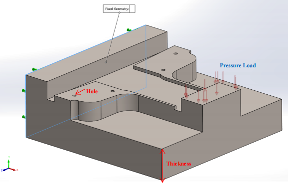
Figure.3. Schematic of the heavy-duty industrial fixture, encompassing the position of constains and pressure load

Figure.4. The 3D Isometric view, third-angle projections, and geometrical dimensions of the heavy-duty industrial fixture.
2023-10-19
Finite Element Analysis