ELEC209 ELECTRICAL CIRCUITS & POWER SYSTEMS FIRST SEMESTER EXAMINATIONS 2019/20
Hello, dear friend, you can consult us at any time if you have any questions, add WeChat: daixieit
ELEC209
FIRST SEMESTER EXAMINATIONS 2019/20
ELECTRICAL CIRCUITS & POWER SYSTEMS
1. a) i) State why in a three-phase system, transformers in the distribution and local substations must have a secondary winding connected as Y (start) rather than Δ (delta).
ii) State, with a proper justification, a possible and quick way to check if there is a fault in a three-phase system that is arranged as four-wire Y.
b) i) A three-phase Y-connected load is supplied by a balanced three-phase Y-connected source with a phase voltage of 120 V. If the line impedance and load impedance per phase are 1 + j1 Ω and 20 + j10 Ω, respectively, determine the line currents and load voltages.
ii) A balanced three-phase delta-connected load with per phase impedance 10 + j7.54 Ω is connected to a balanced three-phase Y voltage source with phase voltage of 220 V. Determine the line currents and load (phase) currents.
c) Two three-phase balanced loads are connected to a 240 kV line. Load 1 draws 30 kW at a power factor of 0.6 lagging, while load 2 draws 45 kVAR at a power factor of 0.8 lagging.
i) Calculate the complex power consumed by each three-phase load.
ii) Calculate the total apparent power consumed by both three-phase loads.
iii) Calculate the line currents drawn by each load.
Total 25
2. a) It is required to measure the mutual inductance M formed between two coils practically. With the aid of suitable circuit diagrams and equations, design a laboratory experiment to fulfil this requirement.
b) For the transformer circuit shown in Figure Q2 below:
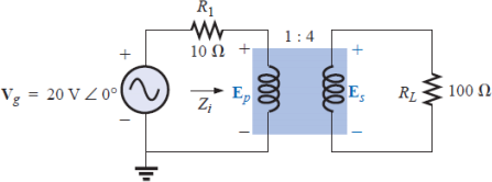
i) Find the input impedance of the transformer Zi.
ii) Find the primary voltage Ep and the secondary voltage Es.
iii) Find the currents in each loop of the transformer circuit.
c) A magnetically coupled pair has a resulting fluxes Φell1 and Φ21 are 0.3 mWb and 0.8 mWb, respectively. If the number of turns for each coil is to be selected as N1 = 500 and N2 = 1000, design the magnetically coupled circuit (i.e. determine L1, L2, M and the coefficient of coupling k) if the driving current is required to be 3 A.
d) The primary coil of a transformer is connected to a 6 V battery. The turns ratio is 1:3 and the secondary load, RL, is 100 ohms. Find the voltage across the load.
e) A transformer with N1 = N2 has a specific application in electrical engineering. Briefly explain why it is needed in electrical system.
Total 25
3. a) For the circuit shown in Figure Q3a:
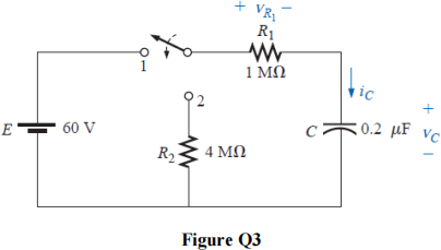
i) Calculate vC, iC, and vR1 at 0.5 s after the switch makes contact with position 1.
ii) The circuit sits in position 1 10 minutes before the switch is moved to position 2. How long after making contact with position 2 will it take for the current iC to drop to 8 μA? How long will it take for vC to drop to 10 V?
b) A 50 Hz alternating (sinusoidal) voltage supply with 100 V peak voltage and 50o phase shift is suddenly applied to a circuit which consists of a resistance R in series with an inductance L = 1 mH.
i) Design the circuit such that the transient has no effect on the circuit.
ii) With proof, re-design the circuit such that the maximum current in the circuit due to transient does not exceed 80 A.
Total 25
4. a) A 20 MVA transformer with 11 kV and 66 kV primary and secondary voltages, respectively, has a reactance of 0.242 ohms referred to the primary. What is the per-unit reactance on the primary side? What is the per-unit reactance referred to the secondary?
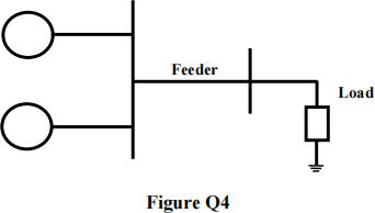
b) Part of a power system is illustrated in Figure Q4. Two synchronous generators are connected in parallel to the same 6.6 kV bus-bars (Gl: 5 MVA, 0.2 pu; G2: 15 MVA, 0.3 pu). The feeder has a reactance of 0.05 Ω/km and is 40 km long. Select 75 MVA as a common power base. Determine generators and feeder per-unit reactances for the given common power base and draw the equivalent circuit of the system.
c) A 600 MVA synchronous generator is star-connected, with 4 poles and a synchronous reactance of 3 Ω. It is supplying 500 MW to an infinite bus at 22 kV, 50 Hz and 0.9 pf (lagging). Calculate the excitation voltage Vo and the load angle δ .
d) Classify overhead transmission lines according to their length and illustrate the equivalent circuit for each class.
e) The turns ratio of a transformer is 20:1 and a peak primary current value of 10 A. Given that the coefficient of coupling k between the primary and secondary coils is 0.6, calculate the secondary current and the referred load to the primary side when the load connected to the secondary winding is (10 + j1) Ω .
Total 25
2023-09-01