ELEC209 ELECTRICAL CIRCUITS & POWER SYSTEMS FIRST SEMESTER EXAMINATIONS 2020/21
Hello, dear friend, you can consult us at any time if you have any questions, add WeChat: daixieit
ELEC209
FIRST SEMESTER EXAMINATIONS 2020/21
ELECTRICAL CIRCUITS & POWER SYSTEMS
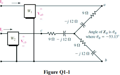
1 a) For the three-phase system shown in Figure Q1- 1, determine the reading of each Wattmeter W1 and W2, then determine the total power delivered to the Y-load. Assume Van = 120 V.
b) For the three-phase system shown in Figure Q1-2, assuming EAN = 120 V and ZY = 6 + j8 Ω,

i) Find the line currents
ii) Find the phase voltages at the load
iii) Find the line voltages at the load.
iv) Find the total real power and reactive power delivered to the load.
c) Figure Q1-3 shows a circuit with three coils in series. Coils L1 and L2 interact, while L3 doesn’t interact with other coils. Find the total inductance of the circuit LT.

Total 25
2. a) For the circuit shown in Figure Q2- 1,
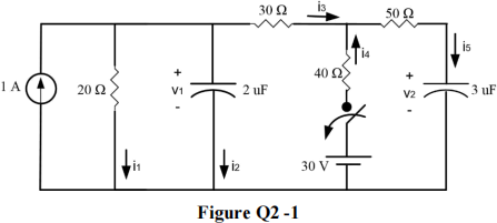
Find the voltages v1 and v2, and the currents i1, i2, i3, i4 and i5 immediately after closing the switch.
b) For the circuit shown in Figure Q2-2 below:
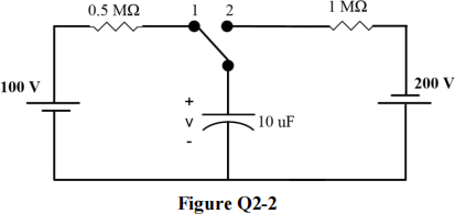
The switch was in position 1 for a long time. It is then thrown to position 2 for 2 s, then returned back to position 1.
i) Find the mathematical expression(s) for the voltage v fort ≥ 0.
ii) Find the mathematical expression(s) for the capacitor current fort ≥ 0.
c) It is required to design an RC timer circuit, with a switch, a capacitor C (1 µF) and a resistor R, all in series with a 50 V power supply. Closing the switch then opening it after 5 s produces 3 V across the capacitor. Design this circuit (i.e. find the value of R) to satisfy this condition.
d) A 0.1 µF capacitor is initially charged to 230 V, then discharged through a 3 MΩ resistor. Find the capacitor voltage after 0.2 s from the start of discharging.
Total 25
3. a) A power system is shown in Figure Q3 below. A 50 MW load with 0.8 power factor lagging connected to the 33 kV substation transformer is required to maintain 30 kV. [Note that the system is a three-phase one.]

i) Calculate the terminal voltage VG of the generator G in pu.
ii) Redraw a simpler diagram for the system in per unit standard (i.e. all the equipment/components, voltages and currents should be in pu).
b) An electrical heater is rated at 100 V, 500 W. Compute the actual and per unit impedance of the heater. Draw the per unit equivalent circuit of the heater.
c) Find the voltage across the open-circuited secondary of a magnetically coupled circuit when 35 V at 400 Hz is applied to the primary circuit. (self-inductances of coil 1 and 2 are 0.75 H and 0.83 H, respectively, and the coupling coefficient is 0.6).
d) What is the maximum value of the mutual inductance that a magnetically-coupled circuit could have between the two coils involved if each has a self-inductance of 0.4 H and 0.8 H, respectively?
Total 25
4. a) A fossil fuel power plant generating 670 MW is planned to be replaced by a wind farm. Determine the number of wind turbines needed to replace the power plant, assuming average wind speed is 13 m/s, wind turbine efficiency is 39% and blade length is 56 m. [Note: as the number of turbines needs to be an integer, please round your answer to the nearest integer value]. (Assume density of air is 1.25 kg/m3).
b) A three-phase, 22 kV (phase), 500 MVA (phase) star-connected synchronous generator has a per phase reactance Xs of 1.5 pu and supplies 0.8 pu per phase real power at the rated voltage, with a lagging power factor of 0.6 to the load.
i) Calculate the actual excitation voltage and the power angle.
ii) Calculate the actual complex power consumed by the load in MVA (per phase).
c) A three-phase induction machine, with rated frequency of 60 Hz and rated voltage of 220 V, has the following parameters: R1 = 0.39 Ω, R2' = 0.14 Ω, x1 = 0.35 Ω and x2' = 0.35 Ω. Calculate input power of the machine, stator current, slip and power factor under rated condition (assume the rated speed is 1746 rpm).
d) Two transformers (4:1 and 1:3) are connected together (cascaded). The two transformers are powered by a 10 V AC supply (with a source resistance value of 6 Ω) connected to the primary winding of the first transformer, and a load with 9 Ω is connected across the secondary winding of the second transformer. Find the current in the primary loop of the first transformer and the power delivered to the load.
Total 25
2023-08-29