ELEC 207 INSTRUMENTATION & CONTROL SECOND SEMESTER EXAMINATION 2019/20
Hello, dear friend, you can consult us at any time if you have any questions, add WeChat: daixieit
ELEC 207
SECOND SEMESTER EXAMINATION REPLACEMENTS 2019/20
INSTRUMENTATION & CONTROL
PART A
1. a) A temperature sensor has an accuracy of 0.5 °C, indicated by the manufacturer. This sensor is used to repeatedly measure a constant temperature, giving results which are affected by random noise only. The results are as follows: 2.22 °C, 2.73 °C, 2.09 °C, 2.34 °C, 2.13 °C.
i) Calculate the best estimate of the temperature that can be obtained from the measurement results provided.
ii) Calculate the standard uncertainty of the temperature measurement associated with the sensor accuracy only, assuming a uniform probability distribution of the errors within the accuracy range. Show the mathematical expression used for the calculation.
iii) Estimate the standard uncertainty of the individual temperature measurements associated with random errors only, using the measurement results provided. Show the mathematical expression used for the calculation.
iv) Calculate the overall standard uncertainty of the best temperature estimate calculated in i) above, by combining the uncertainty sources arising from both the accuracy and the random noise. Show the mathematical expression used for the calculation.
b) A Successive Approximation Analog-to-Digital Converter (ADC) is designed to acquire voltage signals containing frequency components from 0 to 80 kHz (excluded), with a resolution below (better than) 10 mV in the specified measurement range from -15 V to 15 V.
i) What is the minimum sampling frequency of the ADC required to correctly acquire the specified input signals? Justify your answer.
ii) What is the minimum number of bits of the ADC required to achieve the specified resolution? Show the calculation steps.
iii) The conversion of each analogue sample into the corresponding digital number takes 0.4 µs per bit. Is the conversion fast enough to allow satisfying both requirements in i) and ii) above at the sametime? Justify your answer.
|
c) |
An anti-aliasing filter is designed to prevent aliasing errors arising from noise added to the signal to be acquired by the ADC in question b) above. i) What kind of filter (low-pass, high-pass, band-pass or band-stop) should it be?
ii) Sketch the magnitude of the frequency response of this filter. Label the axes. iii) Briefly explain a possible drawback of the use of such anti-aliasing filter, in terms of how it may affect the quality of the filtered signal. |
|
d) A measurement circuit is affected by noise arising from electromagnetic interference with a nearby circuit.
i) Is the use of a differential amplifier most effective when the interference is caused by inductive coupling or capacitive coupling? Justify your answer.
ii) What is the most important feature of an instrumentation amplifier that makes it particularly suitable to decrease the effect of the interference in i) above?Explain what that feature means.
Total 25
2. a) A thermocouple has to be chosen for a measurement application that requires a sensitivity around 40 µV/ºC, and a measurement range that goes up to at least 1000 ºC. With reference to Figure Q2.1, identify a suitable thermocouple type (E, J, T, K, C, R or S) for this application.

Figure Q2.1
b) The output voltage of a thermocouple is 2.666 mV, when the reference junction is at 15 ºC. Using Table Q2, determine the temperature measured by the thermocouple.

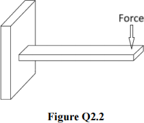
c) Semiconductor strain gauges are chosen to measure the deflection of the cantilever beam shown in Figure Q2.2, because of their high sensitivity to strain. However, semiconductor strain gauges are also very sensitive to temperature variations, and this may result in significant measurement errors.
i) With the aid of a diagram, suggest a possible solution to use semiconductor strain gauges in the specified application without significant errors arising from temperature variations. In the diagram, clearly show how many strain gauges are used and where they are positioned.
ii) Draw an equivalent circuit to show how the strain gauges in i) above should be connected within a deflection bridge circuit that provides an output voltage proportional to the measured strain.
d) An industrial application requires controlling the speed of a motor, and a low-cost solution is sought to measure the motor speed. Which is the most appropriate choice between an incremental encoder and an absolute encoder? Justify your answer.
e) A temperature sensor, initially at 24 ºC, is introduced into an oven at 180 ºC. The sensor has a first-order transient response, with a time constant of 7 s. Write the expression for the sensor output temperature as a function of time, and calculate the waiting time required for the output to reach 170 ºC.
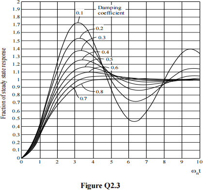
f) An accelerometer is designed with a natural angular frequency ωn = 12 rad/s and a static sensitivity K = 0.5 V/g. Using the normalised step response curves shown in Figure Q2.3:
i) Determine an appropriate value of the damping ratio ξ so that the maximum (peak) output voltage produced by the accelerometer in response to a stepacceleration of 6g is 3.3 V.
ii) Determine an approximate estimate of the time required for the output voltage to reach the peak value, with the damping ratio determined in i) above.
iii) Sketch the step response that would be obtained if the damping ratio were 0. Clearly annotate the vertical axis with quantitative values for the fraction of steady state response.
Total 25
PART B
3. You are working as a control engineer for a company that is designing a commercial spacecraft that can transport people around the world much faster than is possible today. Three salesmen have been discussing the response of the spacecraft to inputs to the control system you are designing.
a) The spacecraft can be approximated as a (stable) under-damped second order system. Sketch the time-response to unit step input. Clearly indicate a non-zero steady-state error of more than 100%, a percentage overshoot of more than 10%, the peak-time and the settling time.
b) You have convinced the first salesman that a percentage overshoot of 15% is appropriate. What damping ratio would achieve this amount of overshoot?
c) The first salesman believes that the settling time should be no more than 2 seconds. What range of natural frequencies could achieve this?
d) The second salesman believes that the peak time should be no more than 1 second. What range of natural frequencies could achieve this?
e) What range of natural frequencies would satisfy both salesmen?
f) What natural frequency would you choose? Why?
g) The third salesman is concerned that there is a finite steady-state error in response to the unit step and you have suggested that a PID controller could address this concern. What are the zeros of a PID controller?
h) What feature of adding a PID controller to the open-loop transfer function would help address the third salesman’s concerns?
i) The third salesman is unsure and thinks that a competitor company is using the electronic circuit shown in figure Q3.1. By considering differential equations, deduce the transfer function of this circuit. Assume that the circuit is isolated and that the input is a voltage of x(t) and the output is a voltage of y(t).
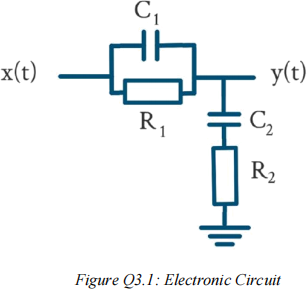
j) Why will the circuit in Figure Q3.1 not address the third salesman’s concerns?
Explain your answer with reference to the poles and zeros of the transfer function for the PID controller and for the electronic circuit shown in Figure Q3.1.
Total 25
4. A central heating system has transfer function

a) You are designing a negative feedback control system that will use a cascade proportional controller with transfer function K. Draw a block diagram describing the control system. Clearly indicate the plant, the controller, the reference input and the output signal.
b) What is the closed loop transfer function? Express your answer in terms of G1(s) and K.
d) Draw the root locus that describes the movement of the closed-loop poles asK is varied. Clearly indicate the position of the closed-loop poles when K=0 and K=∞ .
e) What shape in the complex plane is described by the locus of complex poles that have a natural frequency of ω? Clearly state how increasing ω would alter the locus.
f) What shape in the complex plane is described by the locus of poles that have a damping ratio of β? Clearly state how increasing β would alter the locus.
g) Another central heating system has a transfer function

Using Routh-Hurwitz or otherwise, determine the stability of this second central heating system.
h) What is the system type for G2(s)?
i) Calculate the steady-state error that will result when K=2 and a unit step is input to a closed-loop control system with this second central heating system as the plant.
Total 25
2023-08-26