EEE8154 CONTROL OF ELECTRIC DRIVES SEMESTER 1, 2022/2023
Hello, dear friend, you can consult us at any time if you have any questions, add WeChat: daixieit
EEE8154
SEMESTER 1, 2022/2023
CONTROL OF ELECTRIC DRIVES
Question 1
1a) Describe flux-weakening operation in dc motor drives. Explain why flux-weakening is used and its impact on the torque producing capability of a dc machine. Use graphs and equations to support your answer. [8 marks]
1b) A separately excited dc motor’s armature voltage equation can be written as:

The back-emf and the torque can be calculated using:

The motor is supplied through an H-bridge and has the following parameters:
Ra= 2.1 Ω, La = 36 mH, ke = kT = 0.335 V/rpm
Calculate the maximum steady state speed at which the machine can produce a torque of Te = 60 Nm when the available dc-link voltage is Vdc = 350 V. [6 marks]
1c) If the user requires the operating speed of the machine to be
10% more than what you calculated in part (b) without increasing the dc-link voltage (i.e. keeping Vdc = 350 V), calculate the new value of torque that the machine can develop at 10% higher speed with no flux-weakening. [8 marks]
1d) Keeping the same armature current as in part (b), repeat part (c) but now assuming flux-weakening condition.
Explain in detail the results you have obtained in parts (c) and (d). [8 marks]
Question 2
2a) The stator voltage equation of a permanent magnet synchronous machine (PMSM) in the rotor flux-oriented dq frame is given as:
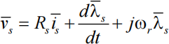
with the vectors defined as: 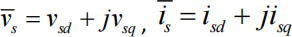 and
and 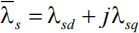
The stator flux-linkage vector is given as:
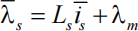
where λm is a constant flux produced by the rotor permanent magnets.
Substitute for the stator flux-linkage vector in the stator voltage equation and then dot product the resulting equation with the vector ![]() is . Identify the various power terms you obtain on the left-hand side and the right-hand side of the equation. [12 marks]
is . Identify the various power terms you obtain on the left-hand side and the right-hand side of the equation. [12 marks]
2b) Further develop the equations in part (a) to obtain an expression for the electromagnetic torque generated by a PMSM with p number of pole-pairs. [4 marks]
2c) The shaft of a rotor flux-oriented vector controlled PMSM is held firmly at standstill by a load machine that applies a torque of TL = 15 Nm. Assume isd = 0 and calculate isq that must be supplied to the PMSM to keep the shaft from rotating i.e., to maintain ωm = 0.
The parameters of the machine are:
Pole-pairs = 4, Rs = 0.37 Ω, Ls = 2.4 mH, λm = 0.125 Vs [4 marks]
2d) The machine of part (c) is now required to turn the load at a constant speed of 1000rpm by sustaining the load torque of TL = 15Nm. Assuming that the friction coefficient is B = 0.02Nms, calculate:
(i) the new value of the q-axis current [5 marks]
(ii) the magnitude of the stator phase voltage. [5 marks]
Question 3
3a) For a squirrel-cage induction machine, the rotor flux-linkage dynamic equation is represented in the block diagram of Figure 1 below.
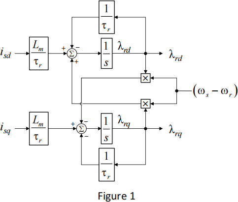
By analysing the above figure, write down the d and q-axis rotor flux- linkage scalar equations. Combine the two equations to express them in a single vector equation. [8 marks]
3b) A rotor flux-oriented vector controlled 4-pole induction motor with Lm = 0.04 H and Lr = 0.05 H is running in a steady state condition with a constant speed and torque. At a particular instant, the stator current and the rotor flux-linkage vectors are determined in the stationary reference frame as:

Using the following expression, calculate the torque developed by the machine:

where the symbol ^ indicates a vector product. [6 marks]
3c) For the machine and the operating condition of part (b), the mechanical speed is 150 rpm. If the rotor resistance is 0.25 Ω, determine the stator frequency in Hz to produce the torque you calculated in part (b). [8 marks]
3d) Assume that the machine is turning a fan type load that has a torque profile given by TL = k负m(2) and there is no friction:
(i) using the steady-state speed given in part (c), determine a value for k. [2 marks]
(ii) determine the new stator frequency (in Hz) if the q-axis current in part (b) is halved. [6 marks]
Question 4
4a) The Figure 2 below shows a three-phase two-level power electronic converter with a capacitive dc-link. The power electronic switches Q1 through Q6 can be commanded to open and close to apply different voltages across a three-phase load. The load is balanced three-phase is star connected, as shown. Draw the circuit diagrams and show different phase-to-neutral voltages that can be produced at the load.
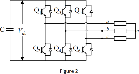
4b) For the three-phase power converter shown above, state which switch closing combinations are prohibited and explain why. [4 marks]
4c) The dc-link voltage of a three-phase inverter is Vdc = 330 V, calculate the maximum phase-to-neutral voltage that can be applied to a three-phase star-connected load. [4 marks]
4d) In space vector modulation, for a given sector S and a per-unit voltage vector given as 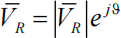 , the duty cycles d1 and d2 for two adjacent active states of the inverter can be calculated as:
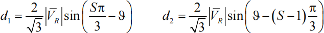
A voltage vector of 160 V magnitude at an angle of 135。from the positive α-axis is to be produced. Calculate the per-unit voltage vector magnitude by using the dc-link voltage as given in part (c) and then use the above expressions to determine the duty cycles d1 and d2. Draw a vector diagram on the αβ-plane and show the location of the voltage vector and identify the inverter states to which d1 and d2 apply. [10 marks]
2023-08-25