EEE8154 Control of Electric Drives SEMESTER 1, 2021/2022
Hello, dear friend, you can consult us at any time if you have any questions, add WeChat: daixieit
EEE8154
SEMESTER 1, 2021/2022
Control of Electric Drives
(AC Part)
Question 1
1a) Explain the structure of and power flow in two-quadrant and four-quadrant three-phase ac drives. [8 marks]
1b) A three-phase ac motor, with a rotor moment of inertia of
0.001 kg m2, is supplied from a voltage source inverter whose dc-link capacitance is 1200 μF. The dc-link voltage is measured as 600 V and the motor is operating at a steady state speed of 4000 rpm. Assume there is no braking resistor fitted and there are no losses in the motor and the inverter. Using the energy balance equation, calculate the final dc-link voltage if the machine is to be brought to a standstill (i.e. rotor speed = 0rpm). [6 marks]
1c) For the machine of part b, calculate the new dc-link capacitance required if the final voltage is to be limited at 660 V. [6 marks]
1d) Comment on the results you have got in parts b and c and explain different solutions that can be used to keep the maximum dc-link voltage of part c without increasing the dc-link capacitance. [10 marks]
Question 2
2a) The stator voltage equation of a permanent magnet synchronous machine in the rotor flux-oriented dq-frame can be written as:
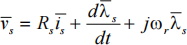
The stator flux-linkage vector appears as a state variable in the above equation. Modify this equation to make the stator current vector as the state variable and write the resulting equation in state-space notation. [7 marks]
2b) A domestic washing machine employs a 16-pole permanent magnet synchronous motor. In steady-state conditions, the motor operates at 120 rpm and the stator voltage vector in the rotor flux- oriented dq-frame is measured as Vs = 32ej 92。 V. The parameters of the machine are given as:
Rs = 2.45 Ω, Ls = 3.1 mH, λm = 0.263 Vs
Determine the magnitude and angle of the stator current vector in the rotor flux-oriented dq-frame. Draw the vector diagram on which show the stator voltage and current vectors and the angle between them. [10 marks]
2c) For the machine of part b, calculate:
(i) the torque developed,
(ii) the converted mechanical power
(iii) the frequency of the stator phase currents in Hz. [6 marks]
2d) Calculate the power factor and efficiency of the motor of part b in the operating conditions given in part b. [7 marks]
Question 3
3a) Explain how flux and torque control can be achieved in an induction motor drive through vector control. Write equations for a squirrel-cage induction machine, draw block diagram to support your answer. In vector control, explain which stator current component gives a fast torque control and why. [10 marks]
3b) For a vector-controlled induction machine, at time t = 0s, the stator current in the rotor flux-oriented dq-frame changes from
I![]() = 14ej 57。 A to I = 14ej 34。 A. Determine the time it will take for the rotor flux-linkage to reach a value of λ
= 14ej 57。 A to I = 14ej 34。 A. Determine the time it will take for the rotor flux-linkage to reach a value of λ![]()
![]() r
r ![]() = 0.539 Vs. Also, calculate the final steady-state magnitude of the rotor flux-linkage vector. The parameters of the machine are:
= 0.539 Vs. Also, calculate the final steady-state magnitude of the rotor flux-linkage vector. The parameters of the machine are:
Rr = 0.44 Ω, Lm = 51 mH, Lr = 55 mH
Hint: For the frequency domain transfer function  , the time domain expression for
 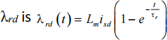 [8 marks]
3c) If the machine of part b has 4 poles, calculate the steady-state torque before and after the change in the current vector. [4 marks]
3d) For the machine of part b, calculate the steady-state slip-speed (in rad/s) before and after the change in the current vector.
Comment on the results you got in parts c and d. [8 marks]
Question 4
4a) For a three-phase voltage source inverter, with a dc-link voltage of Vdc, the vertices of the regular hexagon in the figure below represent the position of various voltage vectors that can be produced at the terminals of a star-connected load (neutral isolated). The length of each vertex from the centre of the hexagon is ⅔Vdc, as marked in the figure. The figure also shows an inscribed circle that represents the maximum amplitude of the voltage vector that can be traced in linear regulation range for the given dc-link voltage.
Determine the radius of this inscribed circle in terms of the dc-link voltage Vdc. Show all your derivation steps.

[8 marks]
4b) The dc-link voltage of a three-phase voltage source inverter is Vdc = 430 V. Calculate the maximum phase-to-neutral and phase-to- phase voltages that can be produced at the load terminals.
Hint: Use the expression you obtained in part a for phase-to-neutral voltage. [6 marks]
4c) For a three-phase ac motor drive, the space vector modulation algorithm calculates the following phase duty cycles:
da = 0.764, db = 0.236, dc = 0.54
with the reference voltage vector lying in sector 6.
Using expressions from an appropriate row of the following table, calculate d1 and d2. What will be the duty cycle (d0) for the zero
state?

[8 marks]
4d) Using the dc-link voltage as given in part b i.e. Vdc = 430 V, calculate the magnitude of the reference voltage vector for the SVM algorithm of part c. Also find the angle of this vector. [8 marks]
2023-08-25