ELEC209 ELECTRICAL CIRCUITS & POWER SYSTEMS FIRST SEMESTER EXAMINATIONS 2021/22
Hello, dear friend, you can consult us at any time if you have any questions, add WeChat: daixieit
ELEC209
FIRST SEMESTER EXAMINATIONS 2021/22
ELECTRICAL CIRCUITS & POWER SYSTEMS
1. a) The switch in the circuit shown in Figure Q1-1 has been closed for a long time and is
opened at t = 0.
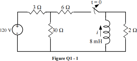
i) Calculate the initial value of the current i.
|
ii) |
Calculate the initial energy stored in the inductor. |
|
|
iii) |
What is the time constant of the circuit for t > 0 ? |
|
|
iv) |
What is the mathematical expression for i(t) fort ≥ 0 ? |
|
|
v) |
What percentage of the initial energy stored in the inductor has been dissipated in the 2 Ω resistor at 5 ms after the switch has been opened. |
|
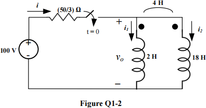
b) There is no energy stored in the circuit shown in Figure Q1-2 at the time the switch is closed. Find the mathematical expressions for i(t), vo(t), i1 (t) and i2 (t) fort ≥ 0.
Total 25
|
a) |
A balanced three-phase Y-connected generator has an internal impedance of 0.2 + j0.5 Ω per phase and an internal voltage of 120 V per phase. The generator feeds a balanced three-phase ∆-load having an impedance of 118.5 + j85.8Ω per phase. The impedance of the line connecting the generator to the load is 0.3 + j0.9 Ω per phase. Assume the system has a positive phase sequence. i) Calculate the three line currents. ii) Calculate the three phase voltages at the load. |
|
iii) Calculate the three phase currents of the load.
iv) Calculate the efficiency of the given three-phase system.
b) A balanced three-phase load requires 600 kW at a lagging power factor of 0.7. The load is fed from a line having an impedance of 0.003 + j0.02 Ω per phase. The line voltage at the terminal of the load is 500 V.
i) Calculate the magnitude of the line current
ii) Calculate the magnitude of the line voltage at the sending end of the line.
iii) Calculate the power factor at the sending end of the line.
iv) Calculate the transmitted (i.e. the sending end) power.
c) Two sets of measurements are made on a two-port resistive circuit. The results are as follows:
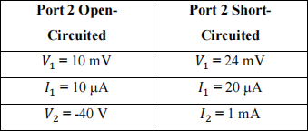
Use a suitable two-port network parameters to represent the circuit.
Total 25
3. a) A power transmission line is represented by a series impedance Z = 5 + j40 Ω. Assuming the base voltage is 140 kV (line) and the base power is 20 MVA (three-phase power),
i) Express transmission line impedance in per unit.
ii) Find the base current of the system.
![]() b) A power system is shown in Figure Q3 below. Draw a simpler representation (i.e. equivalent circuit) for this system using the per unit concept. Show all the necessary steps (Note: Use 30 kVA and 240 V as your base values for the entire system. Reactances X1 and X2 are expressed in per unit, pu).
b) A power system is shown in Figure Q3 below. Draw a simpler representation (i.e. equivalent circuit) for this system using the per unit concept. Show all the necessary steps (Note: Use 30 kVA and 240 V as your base values for the entire system. Reactances X1 and X2 are expressed in per unit, pu).

![]() c) It is required to replace a fossil fuel powerplant by a wind farm, and you have been hired as the engineer to carry out this task. After studying the site, you have found out that the average wind speed is 13 m/s. You have decided to use wind turbines with 42% efficiency and 50 m blade length. Design the farm (i.e. determine the number of wind turbines needed to replace the power plant), assuming the density of air is 1.25 kg/m3 and the fossil fuel powerplant generates 750 MW on average. [Note: the number of turbines must be an integer].
c) It is required to replace a fossil fuel powerplant by a wind farm, and you have been hired as the engineer to carry out this task. After studying the site, you have found out that the average wind speed is 13 m/s. You have decided to use wind turbines with 42% efficiency and 50 m blade length. Design the farm (i.e. determine the number of wind turbines needed to replace the power plant), assuming the density of air is 1.25 kg/m3 and the fossil fuel powerplant generates 750 MW on average. [Note: the number of turbines must be an integer].
d) A three-phase synchronous generator with terminal line voltage of 60 kV is required to have line current of 6.5![]() -40˚ kA. Determine the complex power supplied by the generator and the power factor.
-40˚ kA. Determine the complex power supplied by the generator and the power factor.
Total 25
|
4. |
a) |
A three-phase 4-pole induction machine, with rated frequency of 50 Hz and rated voltage of 380 V, has the following parameters: R1 = 0.5 Ω, R2(′) = 0.2 Ω, x1 = 0.4 Ω and x2(′) = 0.4 Ω. (Assume the rated speed is 1455 rpm). i) Calculate the rated slip. ii) Calculate the starting and rated stator currents. iii) Calculate the input power and the power factor of the machine under rated condition. |
|
b) A three-phase, 10 kV, 750 MVA, star-connected synchronous generator has a per phase reactance of 2 pu and supplies 1.2 pu per phase real power at the rated voltage, with a leading power factor of 0.75 to the load.
i) Calculate the actual excitation voltage and the power angle.
ii) Calculate the actual complex power consumed by the load.
iii) Is the generator overexcited or under excited? Explain your answer.
d) The turns ratio of a transformer is 20:3. Calculate the referred load to the primary side of this transformer when the load connected to the secondary winding is 10 + j5 Ω .
Total 25
2023-08-25