EEE8014 CONTROL OF ELECTRIC DRIVES SEMESTER 2, 2019/2020
Hello, dear friend, you can consult us at any time if you have any questions, add WeChat: daixieit
EEE8014
SEMESTER 2, 2019/2020
CONTROL OF ELECTRIC DRIVES
SECTION A
Question 1
1a) A separately excited DC machine is modelled using:

i) Assuming that the flux (ψ) is a constant, convert the above equations to the s-domain [3 Marks]
ii) Then develop the transfer function I a(s) Va(s) [6 Marks]
1b) Two time constants can be defined as Ta =R(L)a(a) and Tm = K2(J)ψ(R a)0(2) .
During field weakening the flux is described by ψ = bψ0, where ψ0 is the rated flux. Using the developed transfer function ![]() equate this to the standard 2nd order form and derive
equate this to the standard 2nd order form and derive
expressions for damping factor (ξ) and natural frequency (幼n) in termsof Ta, Tm, and b. [9 Marks]
1c) A separately excited DC motor drive uses an H-bridge converter to supply voltage to the armature winding. A constant flux
level has been established in the machine. The H-bridge
converter is switched using unipolar pulse width modulation. The motor parameters are kψ = 0.1 Nm/A, Ra = 0.1 Ω, and La = 8 mH. The drive is used for a hoist application where a constant load torque of 2 Nm must be produced at standstill. Assuming the DC bus voltage is 24 V, calculate the modulation index. [6 Marks]
1d) Assuming the operating conditions of 1c), for a carrier frequency of 10 kHz, estimate the peak to peak value of the armature current ripple. [6 Marks]
Question 2
2a) A DC motor drive employs a cascaded control structure as shown in Fig.1. The inner armature current loop has been previously tuned to give a first order closed loop response and is represented in the diagram by a first order transfer function. The mechanical components of the drive have been modelled with inertia (J) and a friction coefficient (B). The motor flux is assumed to be constant and the relationship between armature current and torque given by Te = kψia. The speed loop is controlled by a proportional term kp.
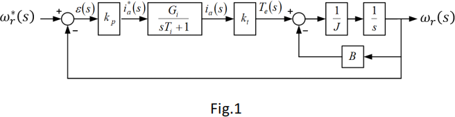
i) Define the open loop transfer function for the system in Fig.1.
ii) Derive an expression for the closed loop transfer function
幼T(s)
幼![]() .
.
For the final expression ensure that the denominator isolates the s2 term. [10 Marks]
2b) By comparing the denominator of the closed loop transfer function with the standard 2nd order form, derive expressions for natural frequency (幼n) and damping factor (ξ) in terms of the other system parameters. [5 Marks]
2c) Assuming a critically damped closed loop response (ξ = 1), calculate the speed loop gain kp when the system parameters are:
J = 0.35 kgm2, kt = 1.5 Nm/A, Gi = 2, Ti = 0.05 s, B = 2.5 [6 Marks]
2d) Calculate the steady state speed error (ε(s)) when the demanded speed 幼r(∗) is 5rad/s. [9 Marks]
Question 3
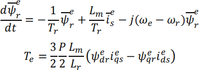
3a) In an induction machine, the relationship between the rotor
e ![]() e
e
flux vector (ψr), and the stator current vector (is),can be
described by the following space vector differential equation:
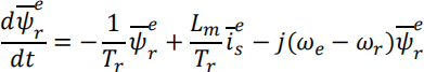
The model parameters are defined as:
Lm = mutual inductance, Tr = rotor time constant, 幼e = excitation frame angular velocity, and 幼r = rotor shaft electrical angular velocity.
Derive a steady state algebraic expression for the rotor flux in terms of the stator current vector. [5 Marks]
3b) A 4-pole, induction machine, vector controlled drive, is operating at a constant speed of 900 revs/min. At a particular ![]() instant the stator current vector is is = (10 + j17) A and the slip is 0.03 per unit. Calculate the e-frame flux components ψ d(e)rand ψq(e)r. The machine parameters are Lm = 0.103 H, Lr = 0.11 H, and Rr = 0.703 Ω . [11 Marks]
instant the stator current vector is is = (10 + j17) A and the slip is 0.03 per unit. Calculate the e-frame flux components ψ d(e)rand ψq(e)r. The machine parameters are Lm = 0.103 H, Lr = 0.11 H, and Rr = 0.703 Ω . [11 Marks]
3c) The electromagnetic torque developed by the drive is given by the following e-frame expression:
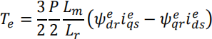
Using the current and flux components calculated in 3b), determine:
i) The torque
ii) The mechanical output power. [4 Marks]
3d) In an induction machine vector controlled drive, it is essential to know the slip frequency (幼slip or 幼2) to allow for accurate orientation of the reference frame, and hence torque control. Show the equation that you would implement in a vector controlled drive which takes into account transient operation of the flux. Using this equation, calculate the slip frequency required for the torque of 3c) [3 Marks]
3e) In an electric drive it is useful to be able to estimate the stator
voltage required corresponding to a particular rotor flux vector
e ![]() e
e
(ψr), and the stator current vector (is), to determine if the inverter is capable of producing this voltage. Using the
following equations, derive a steady state expression which would allow the stator voltage requirement to be estimated.
 [7 Marks]
SECTION B
Question 4
4a) An induction machines dynamic performance can be described by space vector theory. The stator current space vector can be written as:
is(s) = ![]() (ia(s)s + aib(s)s + a2 ic(s)s) where a = exp( j120o)
(ia(s)s + aib(s)s + a2 ic(s)s) where a = exp( j120o)
Carefully derive the scalar expressions which relate the -s rectangular components of is to the phase currents. [6 Marks]
4b) A 3-phase, 2-pole, induction machine drive includes current sensors for measurement of the stator currents. During each
PWM cycle the controller samples the stator phase currents and performs a 3-phase to 2-phase transformation. During one of the cycles the sampled values of the stator currents are given as:
ia(s)s = 17.31 A, ib(s)s = 3.11 A, ic(s)s = −20.41 A
Using the transformations derived in 4a) calculate the rectangular components of the stator current vector. [4 Marks]
4c) During the same PWM cycle the position of the rotor flux vector was determined to beat an angle of θ = 80o with respect to the d-axis of the stator reference frame. Assuming vector controlled conditions are in operation (i.e. the d-axis of the e-frame is aligned with the rotor flux vector),determine the flux (id(e)s) and torque (iq(e)s) producing components of the current. Show diagrams to help explain your calculations and relationships. [9 Marks]
4d) A model for a field orientated induction machine can be described by the following equations:
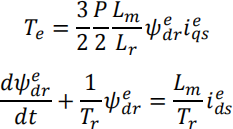
Using the currents calculated in 4c), calculate the rotor flux magnitude and the torque. It can be assumed that the rotor flux has reached a steady state level, the mutual inductance is 91 mH, and the rotor self-inductance is 77 mH. [5 Marks]
4e) During the next PWM cycle the rotor flux vector can be considered to be in the same position as 4c). A speed reversal is to be performed whilst keeping the rotor flux level constant. Determine the magnitude and angle of the stator current vector (is(s)) during this cycle, and the values of the id(s)s and iq(s)s. Show diagrams to help explain your calculations and relationships. [6 Marks]
Question 5
5a) The 3-phase voltage source inverter for a 15 kW, 50 Hz, 4-pole, vector controlled induction machine, has a DC link voltage of
720 V. It can be assumed that the machine is a balanced star- connected set of coils, and each coil can be modelled as a series connected resistance (0.215 Ω) and inductance (0.065 H). It
can also be assumed that the machines star-point is isolated, the inverter is switched using sine-triangle PWM, the inverters power devices are ideal, and that inverter dead-time is not present.
For the inverter, the phase modulation signals applied (m1, m2, and m3) are given as:
m1 = 0.25 sin(15π . t)
m2 = 0.25 sin(15π . t + 120![]() )
)
m3 = 0.25 sin(15π . t + 240![]() )
)
Using this information, calculate the magnitude and phase angle of the fundamental component of the coils currents. [8 Marks]
5b) An induction machine can be modelled by the following e- frame equations:
Show, that by alignment of the e-framed-axis with the rotor flux vector, simplified equations for the flux, torque, and slip frequency can be derived for a vector controlled induction motor. Clearly show all of the steps in the derivation. [8 marks]
5c) The 15 kW, 50 Hz, 4-pole, vector controlled induction machine is used to drive a mechanical load which has an inertia (J) and viscous friction (B). A simplified model of the system is shown
in Fig. 2. The flux producing current demand id(e)s ∗ is held
constant at 14 A and the flux is assumed to have settled to a steady state. The machines parameters are:
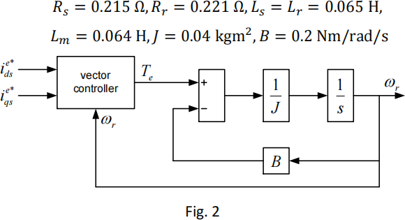
i) If the torque producing current demand iq(e)s * is subjected to astep change from 0 A to 9 A, calculate the torque produced. [4 marks]
ii) Using the simplified model of the system, derive a transfer function T(幼)e(T)![]() for the mechanical part of the system. [3 marks]
for the mechanical part of the system. [3 marks]
iii) In response to the step change in torque, the rotor speed will increase. Calculate the stator frequency applied (in Hz) after the steady state speed has been reached. [7 marks]
Question 6
6a) The block diagram of a digitally controlled DC drive simulation model is shown in Fig.3.

i) Explain the function of the Zero Order Hold (ZOH) and why it is necessary.
ii) What is the purpose of the limiter block on the armature current demand?
iii) What is the purpose of the Delay block?
iv) Explain why the speed loop PI controller has an anti- windup feature.
v) It is common to sample the armature current in synchronism with the inverter PWM carrier signal. Why is this done? [5 Marks]
6b) The DC motor model block in Fig.3 contains a structure based on the following equations:

i) Rearrange these equations into a state space form to find ![]() and ddt(幼)T, which uses armature current and angular velocity as state variables.
and ddt(幼)T, which uses armature current and angular velocity as state variables.
ii) Using these state space equations from parti), draw a MATLAB Simulink block diagram of the DC motor. [8 Marks]
6c) A control loop is employed to hold the armature current constant regardless of the motor back emf. After an initial transient the angular velocity settles to a constant value. Develop an algebraic equation which can be used to predict the steady state speed based on a constant armature current. (Hint: It will result in a quadratic equation). [6 Marks]
6d) A DC motor drive described in 6b) has the following parameters: J = 0.35 kgm2, kφ = 1.5 Nm/A, B = 0.5, ko = 0.005 Nms2 Calculate the steady state angular velocity corresponding to a constant armature current of 5 A. [4 Marks]
6e) The control system described in 6b) uses an H-bridge converter connected to a 240 V DC supply. The converter is switched using pulse width modulation. In a speed loop application, the angular velocity demand is set to a constant value of 50 rads−1. After an initial transient, the motor angular velocity error reduces to 0 rads−1 and the motor electromagnetic torque settles to a steady state value of 10Nm. The armature resistance is 1 Ω and the torque constant is kφ = 1.5 Nm/A.
i) Calculate the back EMF for the angular velocity of 50 rads−1
ii) Calculate the armature voltage required to maintain this steady state condition.
iii) Determine the PWM modulation index (m) output required during this steady state condition. [7 Marks]
2023-08-25