ELEC 207 Instrumentation and Control Second Semester Examinations 2021/22
Hello, dear friend, you can consult us at any time if you have any questions, add WeChat: daixieit
ELEC 207
Second Semester Examinations 2021/22
Instrumentation and Control
PART A
1. You are tasked with testing an RTD. For your testbed, you use the circuit below and
place your RTD in an ice bath at exactly 0°C.
Your RTD has the following characteristics:
R0 (at 0°C) 1000Ω
Sensitivity: 4 Ω/°C
τ = 5s

The ADC has the following characteristics:
Successive approximations
Vref = 3.3V
Sampling rate 20kHz
12-bit Output
In your experiment the ADC supplied the following readings:
3091 3088 3106 3085 3103 3081
a) What temperatures do these readings correspond to? Give the correct equations not just the final value.
b) Calculate the mean, standard deviation, and the uncertainty of the mean for the temperature. Give the correct equations not just the final value.
c) Assuming the standard deviation stays the same, how many repeats would you need to achieve an uncertainty of the mean of 0.1°C.
d) What is the 95.5% confidence interval of your mean, do the current data justify recalibrating your sensor? Explain your choice.
e) Explain median, why can the median be advantageous. (two reasons)
f) If your sensor is in equilibrium with room temperature (20°C). How long do you have to wait before taking a reading after placing the sensor in your ice bath? Explain your choice.
g) If you replaced the current sensor with a sensor with an R0 of 100 Ω. What effect would this have on the noise?
Total 25
2 You are building a system to monitor the angular joint positions of a robotic arm. You will need to monitor the angle of three joints with an accuracy of 0.5° for a range of 300° rotational movement, record this 100 times per second and transmit the data for all three joints back to a control unit. You could build your system using either incremental optical encoders or RVDT.
a) Briefly describe the working principle of an incremental optical encoder and how it could be used to monitor the joints in your robotic arm. Discus what parameters your sensor needs to meet and how well it fits your needs.
b) Briefly describe the working principle of an RVDT and how it could be used to monitor the joints in your robotic arm. Discus what parameters your sensor needs to meet and how well it fits your needs.
c) When using an RVDT you will need to digitise the signal using an ADC. What is the minimum number of bits your ADC needs to monitor your joints?
e) You are transmitting the measurements for all three joints through a single asynchronous serial port. You encode 8-bit frames with parity bit error detection. What minimum bitrate does your port needs to transmit all information to your control unit. Explain your working out.
f) To prevent overloading your robotic arm you use a single point load cell to monitor the weight on your arm. Explain how it works using a circuit diagram and show where you place each strain gauge and how this relates to the circuit diagram. (copy the sketch below to your answer book as a starting point)

PART B
3) a) You have been asked by salesman to design a compensator to improve the overshoot associated with a motor which is being used to control a robotic trapeze artist.
The robotic trapeze artist can be approximated as a second order system, but has six poles. What can you deduce about the position of four of the poles relative to two of the poles?
b) By considering the equation that relates damping coefficient to overshoot, deduce an equation for damping coefficient in terms of overshoot.
c) The uncompensated system achieves an overshoot of 50%. The desired overshoot is 10%. Calculate the damping coefficient for each of the compensated and uncompensated systems.
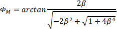
d) What is the increase in phase margin in degrees required to meet the salesman’srequest? You can assume that the phase margin for a second order system is given by the following equation:
e) A colleague is advocating the use of a lag compensator to meet the salesman’srequest. Sketch the bode plot for a lag compensator, parameterised by two break frequencies, a and b. Clearly annotate the bode plot with: the break frequencies; the low frequency gain; the high frequency phase, the low frequency phase and a phase of -90˚. Assume b>10a>b/10 and that the high frequency gain is 0dB.
f) Write a differential equation relating the time-varying voltage, vR(t), across a resistor of resistance, R, and the current through the resistor, iR(t).
g) Write a differential equation relating the time-varying voltage, vL(t), across an inductor of inductance,L, and the current through the inductor, iL(t).
h) Another colleague has advocated that the circuit in figure 3.1 can be used to meet the salesman’s request. Using the answers to questions 3)f) and 3)g) or otherwise, deduce the transfer function of the circuit shown in figure X that converts the input voltage, Vin(t), into the output voltage, Vout(t)?
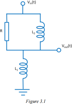
i) Calculate the position of the pole and zero of this transfer function.
j) Does this circuit implement a lag ora lead compensator? Explain your answer.
TOTAL 25
4) a) A system has a transfer function of G1(s) where
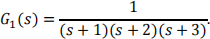
i) A step input is applied to this system. What is the Laplace transform of a step input?
ii) If the Laplace Transform of the input to a system is X(s), the Laplace Transform of the output from the system is Y(s) and the system has transfer function of G1(s), write an expression for Y(s) in terms of G1(s) and X(s).
iii) Using partial fractions or otherwise, write an expression for the time-response that results from applying a step input to a system characterised by a transfer function of G1(s).
iv) The same step input is applied to a second system with transfer function G2(s) where
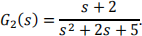
By using partial fractions and by re-expressing the denominator of G2(s) as the sum of two squares or otherwise, write an expression for the time-response that results from applying a step input to a system characterised by a transfer function of G2(s).
b) i) Draw the block diagram of a unity negative feedback system for a plant with transfer function, H(s), and a cascade controller with transfer function, C(s). Clearly identify the reference signal, r(t), the error signal, e(t), and the output signal, y(t).
ii) Write an expression for E(s) in terms of Y(s) andR(s).
iii) Write an expression for Y(s) in terms of E(s), H(s) and C(s).
iv) Using your answers to 4)ii) and 4)iii), derive the closed-loop transfer function for the unity negative feedback system.
v) C(s) describes a PD controller with coefficients of KP=1 and KD=1. Express C(s) in terms of s.
vi) H(s) is defined as follows:
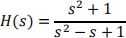
Express the closed-loop transfer function for the unity negative feedback system as a ratio of polynomials in s.
vii) Using Routh-Hurwitz of otherwise, determine if the closed-loop system is stable.
TOTAL 25
2023-08-24