Signals and Systems Workshop 1, 2021
Hello, dear friend, you can consult us at any time if you have any questions, add WeChat: daixieit
Signals and Systems Workshop 1, 2021
Submit a report and your Simulink/Matlab files using the CANVAS assignment link by 5pm, Friday September 3 (Week 6). Ensure that you have familiarised yourself with the University rules around plagiarism before submission. You will have time in the workshops to consult with tutors around your assignment, but should prepare beforehand to make the best use of the available time.
In this workshop you will be analysing a simplified electrical microgrid consisting of a solar PV generator, a battery storage system and a back-up grid connection. The microgrid architecture is as shown in Figure 1.

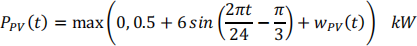
We will assume that a 7kW solar PV is in place and generates power according to a profile (with t specified in hours):
The load is a simplified residential load with a profile given by (again with ? specified in hours):
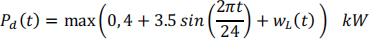
Here  and
and  represent stochastic uncertainties associated with solar generation (eg due to moving cloud cover) and user loads. In this workshop they are modelled as separate normally distributed random signals with mean 0 and variance 5e5, with a new noise signal every 5 minutes (300 seconds).
There is a battery storage system that can supply power,  , but the amount of power available is dependent on the state of the battery. These dynamics will be discussed below.
The load power must be met by the combination of the battery (which can be charged by the solar PV or the grid, but otherwise provides free power during discharge), the PV generation (which is free) and the grid (which has a cost associated with power use,  ).
).
There is no ability to push power onto the grid so at any point in time, the power sourced from the grid is given by the static relationship:

Part 1: Creating the system model (15 marks)
A battery equivalent circuit model is shown in Figure 2. One internal state can be considered as the voltage across the capacitor,  , and the system input can be considered as the difference between the open circuit voltage and the battery voltage,

The other internal state can be considered as the state of charge of the battery,  , which ranges from 0 to 1. When the battery is charging or discharging, t he rate of change of is equal to the battery current,
  , divided by the battery capacity,
  . In addition, the battery also undergoes some gradual leakage which is proportional to the state of charge itself.
The battery power is the product of the battery terminal voltage with the battery current, i.e.:

The state of charge, , and the voltage on the capacitor,  , can be measured using specially designed systems for use in the calculation of the system input. The measurement process for each variable can be modelled as a first order filter operation with a time constant of 1, i.e. for each state there is a transfer function from the true state to the measurement of it that looks like:

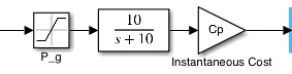
In a similar vein, the Manzie Energy Market Operator (MEMO) applies a filter with a time constant of 10 and unity DC gain to the power requested by the grid before calculating the instantaneous cost of power, i.e.:
Q1: Develop equations of motion of the battery dynamic system including the filters on the states and express the system in a state space form.
Q2: Using an experimental approach, develop the frequency response (Bode plots) of the battery dynamics from  to each of the measured battery states/outputs
  and
and  .
.
Q3: Characterise the step responses times for each of the two states using appropriate time domain specifications.
Q4: Create a simulation diagram of the entire microgrid that has the cumulative cost of grid power as the output, and has exogenous (i.e. non- schedulable) inputs of load and PV power and a controllable input of battery voltage,  .
.
Part 2: Analysis of system performance (15 marks)
To decide whether the battery should be charged or discharged, the following simple (and suboptimal!) rule-based strategy is used to prevent deep discharge or charging (and thus extend the life of the battery). It initially requires a calculation of the requested power from the battery, which is saturated at the maximum power output available:

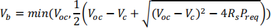
1. If the battery state of charge is less than a threshold,
, charge the battery by setting the terminal voltage by preventing further discharge:

2. If the battery state of charge is in the allowable range
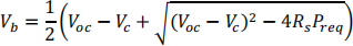
, then set the battery voltage to meet the required power using minimum current:
3. If the battery state of charge is greater than the high threshold,
, only allow discharging of the battery up to a maximum power rate:
Q4: Given the parameter values in Table 1, set up the complete microgrid system in Matlab and/or Simulink and simulate the system for 3 days to estimate the operating cost for the system. [Hint: You may wish to check that all your variables are in SI units or you will end up with some ‘interesting’ results].
Show your source and load trajectories as well as the cumulative cost of electrical power. You may include any other diagrams that you find interesting.
Q5: How long would it take to pay back the initial cost of the battery compared to just relying on a grid connection to service the load?

Part 3: System design (15 marks)
In this part of the workshop, you will conduct an open-ended investigation that will (hopefully) motivate you for further studies in electrical engineering subjects including power systems and control systems. It is also an opportunity to compete with your peers to develop the best solution!
Q6: Investigate varying the size of the battery and the parameters used in the rule-based charging/discharging strategy and see if you can improve the total cost of ownership of the system over a reasonable duration.
Q7: How would your answer change if you had to pay for the solar PV upfront at a reasonable cost?
Discuss your answers and the overall implication of these in the broader context of renewable energy.
2021-09-02