ENG2015 DESIGN AND MANUFACTURE 2 2019
Hello, dear friend, you can consult us at any time if you have any questions, add WeChat: daixieit
Degrees of MEng, BEng, BSc and MSc in Engineering
DESIGN AND MANUFACTURE 2 (ENG2015)
Wednesday 1st May 2019
Topic A: Limits and Fits [16 marks]
Referring to the BS4500 Table of selected fits for holes and shafts:
Q1. Choose the correct sizes of the maximum and minimum diameters for the code 30H9 in mm
a. 30.052 & 30.000
b. 30.062 & 30.000
c. 29.935 & 29.831
d. 30.152 & 30.007
e. 30.000 & 29.948 [1]
Q2. Choose the correct sizes of the maximum and minimum diameters for the code 30f7 in mm
a. 30.052 & 30.000
b. 29.975 & 29.950
c. 30.000 & 29.950
d. 30.052 & 29.959
e. 29.980 & 29.959 [1]
Q3. Using your answers for Q1 and Q2 choose the kind offit you expect from the
code: 30H9f7
a. Ultra Tight
b. Transition
c. Clearance
d. Interference
e. Very Loose [1]
Q4. What kind offit would you expect if you specify the following code 80H11s6?
a. Ultra Tight
b. Transition
c. Clearance
d. Interference
e. Very Loose [1]
Q5. Which of the following is not a general principal or guideline in ‘design for manufacture and assembly’?
a. Use modular design
b. Design with tolerances that are within process capability
c. Use common parts across production lines
d. Shape parts and products for ease of packaging
e. Maximise the use of flexible components [1]
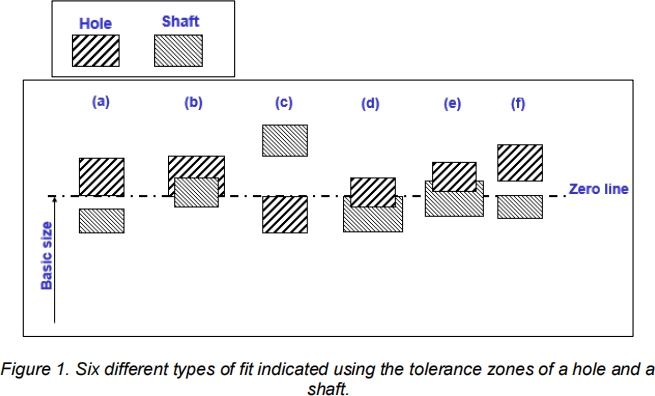
Q6. Figure 1 shows various different types offit (a-f) between hole/shaft
combinations. Decide which of the corresponding descriptions is incorrect:
a. Is a clearance fit shown in a hole based system
b. Is a transition fit shown in a hole based system
c. Is an interference fit shown in a shaft based system
d. Is a transition fit shown in a shaft based system
e. Is a transition fit shown in neither a hole or shaft based system [1]
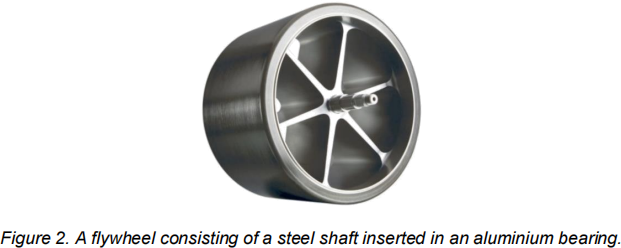
Figure 2 shows a flywheel with a steel shaft inserted inside an aluminium bearing. The hole/shaft fit is specified using the following BS4500 code: 50h6N7 and is
manufactured at room temperature (20oC).
Q7. Referring to Figure 2, state the fundamental deviation of both the hole and the shaft, give your answer in microns.
a. HOLE = 8 & SHAFT = 0
b. HOLE = 8 & SHAFT = 16
c. HOLE = 16 & SHAFT = 0
d. HOLE = 33 & SHAFT = 8
e. HOLE = 8 & SHAFT = 33 [2]
Still referring to Figure 2, assume that the coefficient of thermal expansivity of steel is 12x10-6 . Use this information, Equation (1) and the dimensions of the 50h6N7 fit to answer Questions 8.

Q8. Determine the fundamental deviation of the steel shaft when its temperature is raised to 120oC. Calculate your answer, in mm, correct to 3 decimal places.
a. 50.044
b. 50.060
c. 0.044
d. 0.0600
e. 0.000
f. None of the above are correct
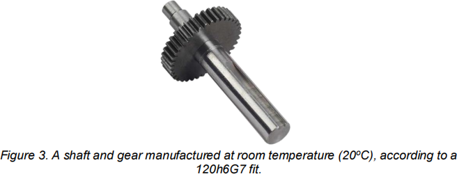
A shaft and a gear are manufactured at room temperature (20oC), according to a 120h6G7 fit. Both the gear and he shaft are manufactured from steel.
Q9. Calculate the allowance of the 120h6G7 fit between the gear and shaft at the least material condition, in microns, then make your choice from the options
below:
a. 12
b. 0.012
c. 34
d. 69
e. 0.034 [2]
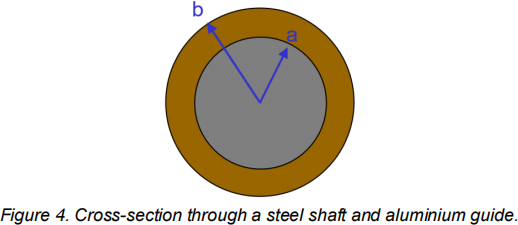
Q10. A steel shaft and aluminium alloy guide are manufactured to a 70H7-p6
interference fit. The outside diameter of the guide is manufactured as 90h7. Choose the correct diameter for the hole and the outer diameter of the guide for the
Maximum Material Condition. Neglect any change in the hole diameter due to any possible interference pressure.
a. HOLE = 70.300 & GUIDE = 90.000
b. HOLE = 70.000 & GUIDE = 89.970
c. HOLE = 70.030 & GUIDE = 89.970
d. HOLE = 70.000 & GUIDE = 90.000
e. HOLE = 90.000 & GUIDE = 70.030 [1]
Q11. Again referring to Figure 4, assume Young’s modulus of steel and aluminium alloy are 200 and 70 GPa respectfully and the Poisson’s ratio for both is 0.3. Use Equation (2) to calculate the pressure at the mating surface for the Maximum
Material Condition. Neglect any change in the hole diameter due to interference pressure. (You should know what the symbols in the equation mean).

a. 15 MPa
b. 20.2 GPa
c. 7 MPa
d. 20.2 MPa
e. 11.0 MPa
f. None of the above
Topic B: Dimensional Measurement and Surface Roughness [14 marks]
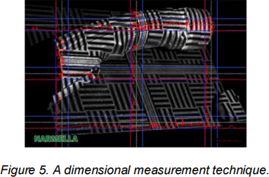
Q12. Figure 5 shows a certain type of dimensional measurement technique. Identify the technique from the list below:
a. Structured light scanning
b. LIDAR
c. Optical Flats
d. Photogrammetry
e. Laser scanner [1]
Q13. On which of the following properties does surface texture have little influence? a. Appearance
b. Friction
c. Wear
d. Ease of painting
e. Crack Initiation [1]
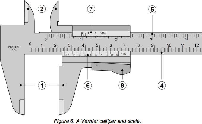
Q14. Your supervisor asks you to measure the diameter of a shaft using a Vernier calliper (see Figure 6 - ignore the circled numbers in the image). Read the lower scale and choose the correct value, if any, from the list. Give your answer in mm:
a. 24.50
b. 2.44
c. 44.4
d. 63.7
e. 24.75 [1]
Q15. How would you best describe the correlation between dimensional tolerance and surface roughness as observed in most manufacturing processes?
a. a roughly negative correlation
b. a strongly negative correlation
c. a strongly positive correlation
d. a roughly positive correlation
e. a very poor correlation [1]
Q16. Given that the symbol, σ, indicates the standard deviation calculated from a set
of measured values of a given component dimension, produced by a given manufacture process. How should we define the natural tolerance of the
manufacture process?
a. –σ to σ
b. -3σ to 3σ
c. -2σ to 2σ
d. -6σ to 6σ
e. -0.5σ to 0.5σ [1]
Q17. Given that the standard deviation calculated from a set of measured values
taken from thousands of manufactured shafts produced by a given manufacture
method is 0.1mm. What percentage of parts do you expect will lie beyond +/-0.02mm from the average shaft diameter?
a. 8.23
b. 12.76
c. 0.27
d. 31.74
e. 4.56 [1]

Q18. As a company’s manufacturing engineer, you are passed design drawings
showing the specified tolerance range for a batch of shafts produced in your factory. The standard deviation of the shaft average diameter produced using your company lathe is 0.05mm. Given that no more than 2,700 shafts per million parts produced
should be defective (i.e. with a diameter outside the stated tolerance range), what is the tolerance range specified in the design drawings? Figure 7 will be useful in
answering this question and you’ll need to know the equation for the PCI. Give your answer in mm.
a. 0.6
b. 0.3
c. 0.1
d. 0.15
e. 0.2 [2]
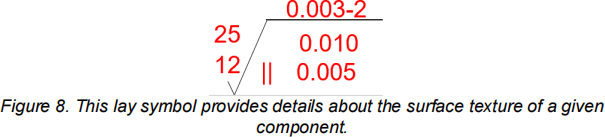
Q19. Referring to Figure 8, state the minimum centreline average surface roughness of the surface.
a. 2 microns
b. 0.01 mm
c. 25 microns
d. 12 microns
e. 0.005 mm
f. None of the above [1]
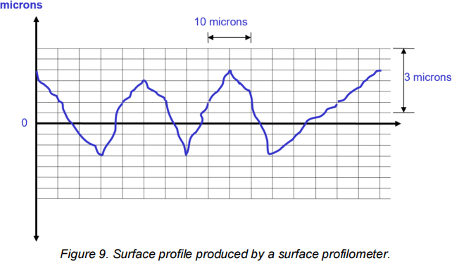
Q20. Figure 9 shows a surface profile. Using this profile, calculate the value of the ‘centre’ or ‘datum’ line in microns, then choose the most reasonable value:
a. 0.6
b. 1.1
c. -0.7
d. 0.8
e. 0.4 [2]
Q21. Given that 7 values of the height away from the datum line were measured
along a surface profile at regular intervals as follows: [1.4, 2.3, -3.9, -1.2, 2.2, -2.1, 2.4] microns. Calculate the root mean square value of the surface roughness using these values, in microns, correct to 2 decimal places.
a. 5.56
b. 2.36
c. -1.54
d. 2.49
e. 2.01 [2]
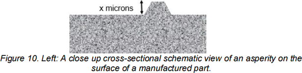
Q22. A basic laser interferometer that uses light of 632nm wavelength is employed to investigate the surface of a manufactured part. The interferometer records full brightness when reflected from both the top and the bottom of an asperity (see Figure 10). Determine the height of the asperity, x, in microns to 3 significant figures. The following equation may be useful:
diff = nλ/2
a. 0.316
b. 0.632
c. 316
d. 632
e. 1.264 [1]
Topic C: Materials Selection [16 marks]
You are asked to find the best material to manufacture the lightest possible tie of
specified length, L, that is both stiff enough to resist deflecting beyond a given
amount, 。, and strong enough not to break when subject to a given load, F. You are also told that the tie must have a minimum value for its thermal conductivity. Given this information, answer Questions 23 to 26.
Q23. Choose the number of objectives involved in this problem
a. 0
b. 1
c. 2
d. 3
e. 4 [1]
Q24. Choose the number of constraints involved in this problem
a. 0
b. 1
c. 2
d. 3
e. 4
f. None of the above
Q25. Choose the number of constraints that are coupled with the objective(s) in this problem
a. 0
b. 1
c. 2
d. 3
e. 4 [1]
Q26. Choose the number of material indices you would expect to find for this problem.
a. 0
b. 1
c. 2
d. 3
e. 4 [1]
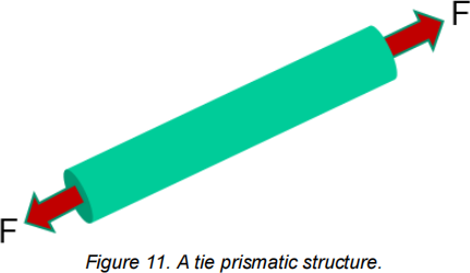
Q27. Figure 11 shows a prismatic tie structure (it has a constant cross section along
its length). Derive an equation relating its cost, C, density, ρ, length, L, cross
sectional area, A and cost per kg, G and then identify this equation from the list below (if any):
a. G = √LAPC
b. A = LPCG
c. P = CGA/L
d. G = APCL
e. A = ![]()
f. None of the above
Q28. Still referring to Figure 11, you are asked design the cheapest / strongest tie
structure possible. The free variables in this problem are the cross-sectional area of the tie and the material. Derive an equation that describes the strength constraint
that the structure has to meet, then choose the appropriate equation from the list
below (if any). Note that F is the applied force, A is the cross sectional area and σf is the yield stress of the material.
a. σf = F. A
b. ![]() ≤ σf
≤ σf
c. σf = F − A
d. σf. F. A = 0
e. ![]() ≥ σf [1]
≥ σf [1]
Q29. Combine your answers from Q27 and Q28 to eliminate the cross-sectional area from the two equations, in order to determine an equation that correctly relates the
applied force, F, tie length, L, density, P, cost per kg, G, yield stress, σf and cost, C. Identify this equation from the list below (if any):
a. F ≥ ![]()
![]() b. σf ≥F
b. σf ≥F![]()
d. σf ≥ ![]()
e. σf ≥ FLPGC [2]
Q30. Continuing from Q29, rearrange the terms in the equation in order to create a material index that, when maximised, will help identify the cheapest material
meeting the strength constraint. Identify this equation from the list below (if any):
a. ![]()
b. ![]()
c. ![]()
d. ![]()
![]() 1
1
e. [2]
Q31. You have been asked to select the best material to manufacture the lightest /
stiffest & strongest tie structure, measuring 1m long, to support a load of 1000N, with an imposed structural stiffness constraint of 10,000Nm- 1. You look up the following equations from your lecture notes:

and using Equations (3) & (4), you plot Figure 12 using CES. Inspect Figure 12 to determine the best material for the job and decide whether this is a stiffness or
strength dominated problem.

a. Lead (strength dominated)
b. Silicon nitride (strength dominated)
c. Boron carbide (stiffness dominated)
d. Boron carbide (strength dominated)
e. Lead (stiffness dominated)
f. None of the above
Q32. You realise that you could use CES in a more general way to make it easier to explore different configurations of S, L, and F (see Equations 3 & 4). You can do this by:
. equating Equations 3 & 4,
. defining two materials indices M1 = p⁄σy and M2 = p⁄E
. substituting the material indices into your equation
. taking logs
in doing so you produce an equation that can be used in a more general way! Identify the equation from the choices below:
a. log(M1) = log(M2) − log ![]()
b. log(M1) = log(M2) + log ![]()
c. log(M1) = log(M2) − log ![]()
d. log(M1) = log(M2) + log ![]()
e. log(M1) = log(M2) + log ![]() [2]
[2]
Q33. You now re-create another CES selection graph plotting the two material
indices on the axes. You examine the effect of changing the configurations of S, L, and F. Use the sets of values
• SET 1= [F=10000N, L=10m, S=100Nm- 1] and
• SET 2 = [F=100N, L=10m, S=10000Nm- 1].
State the y-axis intersect value of the resulting box drag lines for Sets 1 and 2 when the x-axis has a value of 1.

Figure 13. CES plot using M1 and M2 as the axes.
a. SET 1 intersect value = 0.1, SET 2 intersect value = 1000
b. SET 1 intersect value = 1000, SET 2 intersect value =0.1
c. SET 1 intersect value = 100, SET 2 intersect value =1
d. SET 1 intersect value = 0.1, SET 2 intersect value =100
e. SET 1 intersect value = 10, SET 2 intersect value =0.1 [2]
Topic D: Casting and Process Selection [10 marks]
Q34. Various problems and defects can occur during casting of metals, in order to avoid them we have to understand their cause. Options (a) to (e) below list the
causes and defects that can occur during the casting of metals, identify the false cause - defect pairing.
a. Gas entrapment during pouring - produces porosity
b. Turbulence during pouring - damages ceramic moulds
c. Shrinkage during solidification - produces large cavities in the final casting
d. Anisotropic grain solidification - produces mechanical anisotropy in final part e. Dendrite formation during casting of alloys - produces micro-porosity [1]
Given that the down-sprue of a sand mould is 10cm long, its cross-sectional area at the base is 3cm2 and the mould volume is 1300cm3 , consider the flow of molten steel into the mould and use Equations 5-7 to answer Questions 35 to 37. Assume the
acceleration due to gravity is 9.8ms-2. You are expected to know the meaning of the symbols in the equations.
Q=AV
t=VQ
![]()
Equation (5)
Equation (6)
Equation (7)
Q35. Determine the velocity of flow at the bottom of the down-sprue. Calculate your answer in the units of cm/s correct to 1 decimal place then choose the correct option given below.
a. 1.4
b. 0.99
c. 140.0
d. 32.1
e. 99.0 [1]
 Q36. Determine the volumetric flow rate into the mould. Calculate your answer in units of cm3s- 1 correct to 1decimal place, then choose the correct option:
a. 420.0
b. 4.2
c. 297.0
d. 3.0
e. 140 [1]
Q37. Find the mould fill time. Calculate your answer in the units of seconds, correct to 3 significant figures.
a. 249
b. 301
c. 410
d. 209
e. 409 [1]
The total solidification time of a metal plate can be roughly predicted using Chvorinov’s rule as given by see Equation (8).
Eq (8)
Assume the mould constant is 3.5 min.cm-2 and n=2. Given that the ratio between the volume of the mould for the plate and its surface area is 0.3, while the ratio
between the volume of the riser and its surface area is 0.4, determine the answers for Questions 38 to 40.
Q38. Determine the solidification time of the plate.
a. 1.05 minutes
b. 0.315 hours
c. 18.9 hours
d. 18.9 minutes
e. 18.9 seconds
f. None of the above [1]
Q39. Determine the solidification time of the riser.
a. 16 seconds
b. 8.4 seconds
c. 22 seconds
d. 0.22 seconds
e. 8.4 minutes [1]
Q40. Use your answers for Q38 and Q39 to decide whether this is a well-designed mould or not and choose the reason for your answer.
a. Yes, because the riser solidifies after the plate
b. No, because the riser solidifies after the plate
c. Yes, because the riser solidifies before the plate
d. No, because the riser solidifies before the plate
e. Yes, because the riser and plate solidify simultaneously [1]

Figure 14. A schematic showing the classification of key process steps, as defined
by Ashby et al.
Q41. According to the process classification scheme shown in Figure 14, which of the following options, if any, is an incorrectly classified example of a key step?
a. Basic shaping process: (forging)
b. Secondary shaping process: (punching)
c. Property enhancing process: (annealing)
d. Joining process: (riveting)
e. Finishing process (painting) [1]
Q42. According to Ashby’s process selection concept, which of the following options ,
if any, is an incorrectly assigned example:
a. Example of a Function (shaping)
b. Example of an Objective (minimise time)
c. Example of a Constraint (material)
d. Example of a Free Variable (the process)
e. Example of a Constraint (finishing)
f. None of the above, they are all correctly classified examples!

Figure 15. Various components that can be organised according to Ashby’s shape
classification.
Q43. Look at the images in Figure 15 and state which object, if any, has been incorrectly identified according to Ashby’s shape classification scheme:
a. Prismatic / non-circular
b. 3-D / solid
c. Sheet / dished
d. 3-D / hollow
e. Sheet / flat [1]
Topic E: Heat Treatments [14 marks]
Figure 16 shows a continuous cooling transformation diagram for unalloyed steel of eutectoid composition together with three continuous cooling rate curves. Three
specimens of plain carbon steel are heated to 760oC and then cooled at the constant cooling rates shown in the diagram. Refer to Figure 16 to answer Questions 44 to
46.

Figure 16. Continuous cooling transformation diagram
Q44. Name the heat treatment indicated by cooling rate (i)
a. Normalising
b. Chilling
c. Quenching
d. Spheroidising
e. Tempering
f. Full-annealing [1]
Q45. State the microstructure you would expect to find following curve (ii) after 1000 seconds.
a. 50% bainite and 50% retained austenite
b. 100% coarse pearlite
c. 100% bainite
d. 100% martensite
e. 50% bainite and 50% martensite
f. 100% fine pearlite
Q46. Use Figure 16 to describe how you might produce steel with a bainitic microstructure
a. Cool at 35oCs- 1 from 750oC to 300oC then cool much more slowly from 300oC to 20oC
b. Cool at 140oCs- 1 from 750oC to 20oC
c. Cool at 140oCs- 1 from 750oC to 600oC then cool much more slowly from 600oC to 20oC
d. Cool at 140oCs- 1 from 750oC to 400oC then cool much more slowly from 400oC to 20oC
e. Cool at 30oCs- 1 from 750oC to 20oC [2]
Q47. You are provided with a metal alloy part and told that it can be identified by the code: 1080, correctly identify the metal from the list below
a. alloy steel with 0.2 wt% carbon content
b. plain steel with 8 wt% carbon content
c. stainless steel with 0.8 wt% carbon content
d. plain steel with 0.4 wt% carbon content
e. plain steel with 0.8 wt% carbon content [1]
Q48. You are told that the metal alloy part referred to in Q47 has been heat treated so that it now consists of about 90% martensite. What do you expect the other 10% of the steel to be composed of?
a. coarse pearlite
b. tempered martensite
c. bainite
d. retained austentite
e. spheroidite [1]
You are asked to describe the changes that occur during process annealing of a stretch-formed alloy. Read the following short paragraph and correctly identify the missing words in Q49 to Q54.
“The first step during process annealing is the (i) step. During this step the number of (ii) decreases and impurity atoms diffuse back towards the
2023-08-15