KIT308 Multicore Architecture and Programming
Hello, dear friend, you can consult us at any time if you have any questions, add WeChat: daixieit
KIT308 Multicore Architecture and Programming
Assignment 2 — SIMD
Aims of the assignment
The purpose of this assignment is to give you experience at writing a program using SIMD programming techniques. This assignment will give you an opportunity to demonstrate your understanding of:
● the where there is one there is many approach (WTIOTIM);
● structures of arrays;
● the use of SIMD for calculation; and
● the translation of conditional statements into SIMD.
Due Date
11:55pm Friday 24th of September (Week 10 of semester)
● Late assignments will only be accepted in exceptional circumstances and provided that the proper procedures have been followed (see the School Office or this link for details) assignments which are submitted late without good reason will be subject to mark penalties if they are accepted at all (see the School office or this link for details on this as well).
● Forms to request extensions of time to submit assignments are available from the Discipline of ICT office. Requests must be accompanied by suitable documentation and should be submitted before the assignment due date.
Assignment Submission
Your assignment is to be submitted electronically via MyLO and should contain:
● An assignment cover sheet;
● A .zip (or .rar) containing a Visual Studio Solution containing a project for each attempted stage of the assignment (in the format provided in the downloadable materials provided below).
● A document containing:
○ A table of timing information comparing the original single-threaded code (from assignment 1), the provided base code times, and the Stage 1, 2, 3, 4, and 5 SIMD implementation on each scene file (all running with the maximum threads natively supported by your CPU).
○ An analysis of the above timing data.
● You do not need to (and shouldn't) submit executables, temporary object files, or images. In particular, you must delete the ".vs" diretory before submission as it just Visual Studio temporary files and 100s of MBs. Do not however delete the "Scenes" folder or the "Outputs" folder (but do delete the images within this one).
Marking
This assignment will be marked out of 100. NOTE: if your code for a particular stage does not correctly produce the expected output images, you will only be able to receive a maximum of half marks for that stage — see below for more details.
The following is the breakdown of marks:
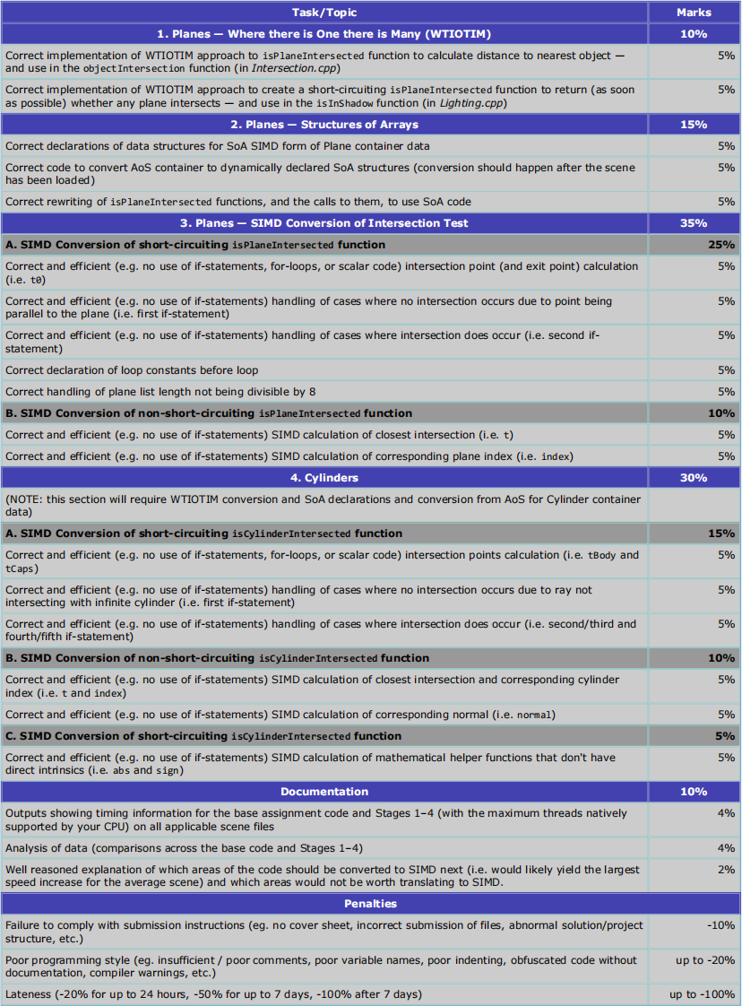
Marking and Correct Images
As SIMD code is very very difficult to debug — as grows exponentially harder as the amount of it grows — there will be limited opportunity in the marking process to determine where exactly mistakes have been made, and even less chance of being able to provide fixes to those mistakes.
As a result, if your code for a stage does not produce the expected image, then you will only be eligible for half marks for that stage of the assignment.
In order to work within this constraint, you should attempt translations into SIMD in very small steps (i.e. a single line at a time, or even a partial line at a time). The lectures will demonstrate this approach to SIMD translation. You will likely receive more marks for a partially complete SIMD translation than a fully complete translation that doesn't work 100%.
Programming Style
This assignment is not focussed on programming style (although it is concerned with efficient code), but you should endeavour to follow good programming practices. You should, for example:
● comment your code;
● use sensible variables names;
● use correct and consistent indenting; and
● internally document (with comments) any notable design decisions.
[NOTE: any examples in the provided assignment materials that don't live up to the above criteria, should be considered to be deliberate examples of what not to do and are provided to aid your learning ;P]
The Assignment Task
You are to modify the (square-based) multithreaded implementation of a "simple" raytracer from the first assignment to take advantage of SIMD instructions. This requires changes across multiple files.
To aid you in this conversion, the sphere/ray intersection code has already been translated into SIMD code (by following the techniques required to do stages 1–3 of the assignment).
From the provided (square-based) multithreaded raytracer implementation, for Stages 1–3 of the assignment you will create multiple subsequent versions that modify the plane implementation as follows:
1. Rewritten functions for the plane/ray intersection tests in a where-there-is-one-there-is-many approach.
2. Translation of array-of-structures (AoS) with structures-of-arrays (SoA) for the plane container.
3. Optimisation of the plane/ray intersection test to take advantage of SIMD.
For Stage 4, you will follow a similar pattern, but for cylinder intersections.
Implementation — SIMD Planes (Stages 1–3)
The following section describes in detail the steps required to complete Stages 1–3 of the assignment. If you complete this step, only then should you attempt Stage 4 and do similar steps for lights. If you complete this step, only then should you attempt Stage 5.
1. Where there is One there is Many
This stage involves replacing the isPlaneIntersected function with two new versions that use the where there is one there is many paradigm.
In order to complete this step you will need to:
● Write two functions that take the entire plane container (or at least a pointer/reference) as an argument and will perform whatever action took place at the calling site. There are two versions as the isInShadow function (in Lighting.cpp) uses a short-circuited approach, exiting as soon as any plane collision is discovered, and the objectIntersection function (in Intersection.cpp) finds the closest plane intersected with (which means it must examine them all).
○ A version of isPlaneIntersected that returns a boolean depending on whether or not a plane intersects with the ray (i.e. stopping as soon as one is found).
○ A version of isPlaneIntersected that returns a boolean (as above), updates its t parameter to be the closest plane that intersects with the ray, and updates its index parameter to specify the index of the closest plane.
2. Structures of Arrays
This stage involves modifying the Scene struct (Scene.h) to store a duplicate of the plane data via structure of arrays rather than the currently existing array of structures (currently in the planeContainer variable).
In order to complete this step you will need to:
● Create a SoA copy of the data that is stored in planeContainer in the Scene struct.
○ NOTE: this means the program has two copies of the plane data, the original one in AoS form and a second one in SoA form. As this assignment predominately only requires changes to isPlaneIntersected (and the sites of the calls to this function) the rest of the code will still use the original AoS version of the data.
● Fill this SoA copy of the plane data after the Scene struct has been loaded (dynamically allocating memory for the SoA representation).
● Rewrite the isPlaneIntersected function to make use of the SoA.
● At times this code update may require conversions to and/or from Vector structs to the equivalently stored data in the SoA. At the end of this stage the program should still produce the same results as the base code. Be thorough in your testing (i.e. test all the scenes) to ensure that everything works correctly before progressing.
3A. SIMD Conversion of isPlaneIntersected function
This stage involves converting the first of the two new version of the isPlaneIntersected function from Stage 2 (the bool returning one) into a SIMD implementation.
In order to complete this step you will need to:
● Convert many of the input parameters (or parts of them) into SIMD-ready values (e.g. the ray starting location and direction need to be converted into a SIMD format).
● Step through the SoA in chunks proportional to the number of value stored in each SIMD variable (i.e. 8).
● Convert the calculation to use SIMD. Care must be taken to correctly deal with the various conditional expressions in the loop. There are two if-statements that must be converted to SIMD code via the use of appropriate masking statements.
● Ensure your approach deals with the situation where the plane count isn't equally divisible by the number in each SIMD calculation (e.g. 9 planes with 8 in each SIMD value). If you follow the approach taken in the provided sphere code to creating the SoA copies, there should be nothing extra to do in this function to make this work.
3B. SIMD Conversion of isPlaneIntersected function
This stage involves converting the latter of the two new versions of the isPlaneIntersected function from Stage 2 (the one that updates its t and index values) into a SIMD implementation.
Most of this conversion is identical to step 3A, and the code can just be copied from that function. It does however require the addition of:
● New variables to keep track of the closest intersection found, and which plane index it was found at.
● Consolidation of the values calculated using SIMD into a single scalar return value. This should be done after the loop finishes.
Hints / Tips
● The techniques required to complete each stage rely heavily on work done in the SIMD tutorials and the step-by step approach shown in lectures — refer to them often.
● When implementing the SIMD stage, it's best to SIMD-ify small portions of code at a time (e.g. even a single line is often a lot) and then perform the rest of the calculation through the existing scalar code, or even compare the result of the SIMD version to the existing scalar code.
● Again for SIMD, it's helpful to render scenes at a greatly reduced size for testing, with an equally small block size, one sample per pixel, and with one thread (e.g. try using ‑input allMaterials.txt ‑size 8 8 ‑blockSize 8 ‑samples 1 ‑threads 1). It may even be helpful to fix the number of rays cast (MAX_RAYS_CAST) to be 1, so that reflection and refraction don't occur. This doesn't produce a very nice image, but images can be easily compared visually for problems (the example is only 64 pixels) and printf statements can be used to verify the correctness of calculations without outputting a huge amount of data (the use of debuggers is somewhat perilous in a multithreaded environment, but that shouldn't be an issue here).
● When converting conditional statements to masks it can be helpful to do this with scalars first (although C/C++ implementations often use 1 rather than 0xFFFFFFFF for true, so the calculations may be different).
● Write functions to output all the elements in a SIMD value for easier printf debugging (I am not a fan of how these types are shown in the debugger).
Implementation — SIMD Cylinders (Stage 4)
The following section describes in detail the steps required to complete Stage 4 of the assignment. You should only attempt this step if you have fully completed (and tested) Stages 1–3.
This stage involves rewriting the isCylinderIntersected function. In order to complete this step you will need to:
● Apply the WTIOTM approach to the isCylinderIntersected function as done for spheres and planes (including creating two versions of the function).
● Create SoA declarations and conversions from AoS for Cylinder container data (in a similar way that this was done for spheres and planes).
● Convert the isCylinderIntersected function to SIMD.
○ NOTE: the non-short-circuiting version of isCylinderIntersected needs to return (via pointers to values) the new value for t, the index of the intersected object, and (in addition to what is required for spheres and planes) the normal at the point of intersection.
Missing Mathematical Functions
There are no definitions in the AVX/AVX2 instruction sets of a couple of mathematical functions needed to translate isCylinderIntersected to SIMD:
● The abs function (as defined in cstdlib, but mapping to fabsf), as defined here.
● The sign function (as defined in Primitives.h).
You must define replacements for these functions that work on a SIMD vector.
Hints / Tips
● All the hints/tips from the stages 1–3 apply here (i.e. complete this in small steps, use 8x8 images as tests, use a lot of printfs, etc.).
● The calculation and logic for the cylinder/ray intersection test is significantly more complex than for the plane/ray intersection test, so make sure you test each small change thoroughly – preferrably with the testing scripts, not just by examining the image by eye.
Documentation
When completing either stage of the assignment you should provide:
● timing information for each scene file for the average time (to 1 decimal place) taken over 5 runs for a render using a thread count supported by your the number of logical processors in your system and a block size of 16. See a later section for an example format for this timing table; and
● an explanation of the results (e.g. why there's no difference between the performance of stages 1, 2, and 3 (NOTE: this is a made up example and isn't necessarily what to expect), or why a particular type of implementation works well (or poorly) on a particular scene, etc.). This explanation should be with respect to the CPU on the system on which you ran the tests, and you should discuss how the architectural features of the CPU explain the results.
Tests / Timing
The following table lists all the tests that your code needs to generate correctly at each stage. It also shows the timing tests that need to be performed in order to fully complete the documentation section of the assignment. Fully completing this tests may take up to an hour (with the 5 required runs) on some hardware, so plan your time accordingly.
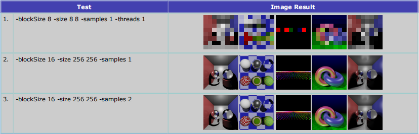
In order to confirm your images match the images created by the base version of the assignment code, it's strongly recommended you use an image comparison tool. For part of the marking for this, Image Magick will be used (as it was in Assignment 1).
The timing tests need to be run in the "Release" build configuration as well as "FastRelease" build configuration. The "Release" mode uses a "strict" floating-point model setting to ensure that the SIMD conversion doesn't introduce calculation inconsistencies with the base code, and the "FastRelease" allows for inaccuracies in order to prioritise speed. Accordingly, only the former should be used for the comparison tests with ImageMagick (and its this version that will be used by the marker to perform these tests) — the latter will show a varying amount of difference depending on the test.
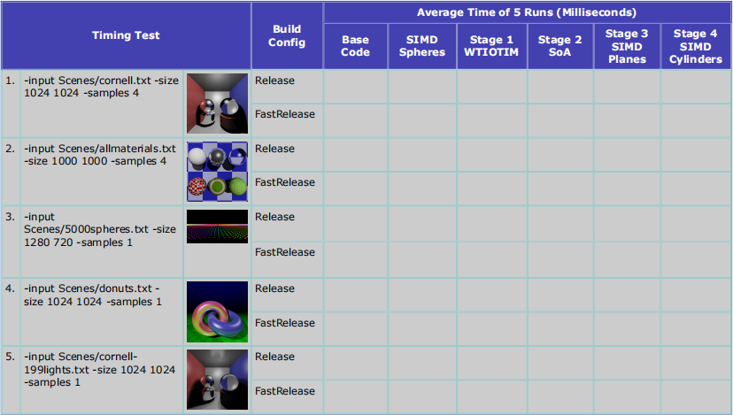
The following tests will be run on your code for each scene file. You also might find the 8x8 tests useful for your SIMD code conversion:
Provided Materials
The materials provided with this assignment contain:
● The source code of the base multi-threaded version of the raytracer (i.e. a solution to Assignment 1).
● The source code of the base multi-threaded version of the raytracer with a SIMD implementation of the Ray-Sphere test.
● A set of scene files to be supplied to the program.
● A set of reference images for testing.
● Some batch files for testing purposes.
Download the materials as an ZIP file.
Source Code
The provided MSVC solution contains 6 projects.
RayTracerAss2
The provided code consists of 19 source files.
● Raytracing logic:
○ Raytrace.cpp: this file contains the main function which reads the supplied scene file, begins the raytracing, and writes the output BMP file. The main render loop, ray trace function, and handling of reflection and refraction is also in this file.
○ Intersection.h and Intersection.cpp: these files define a datastructure for capturing relevant information at the point of intersection between a ray and a scene object and functions for testing for individual ray-object collisions and ray-scene collisions.
○ Lighting.h and Lighting.cpp: these files provide functions to apply a lighting calculation at a single intersection point.
○ Texturing.h and Texturing.cpp: these files provide functions for the reading points from 3D procedural textures.
○ Constants.h: this header provide constant definitions used in the raytracing.
● Basic types:
○ Primitives.h: this header contains definitions for points, vector, and rays. It also provides functions and overloaded operators for performing calculations with vectors and points.
○ SceneObjects.h: this header file provides definitions for scene objects (ie. materials, lights, spheres, planes, and cylinders).
○ Colour.h: this header defines a datastructure for representing colours (with each colour component represented as a float) and simple operations on colours, including conversions to/from the standard BGR pixel format.
● Scene definition and I/O:
○ Scene.h and Scene.cpp: the header file contains the datastructure to represent a scene and a single function that initialises this datastructure from a file. The scene datastructure itself consists of properties of the scene and lists of the various scene objects as described above. The implementation file contains many functions to aide in the scene loading process. Scene loading relies upon the functionality provided by the Config class.
○ Config.h and Config.cpp: this class provide facilities for parsing the scene file.
○ SimpleString.h: this is helper string class used by the Config class.
● Image I/O:
○ ImageIO.h and ImageIO.cpp: these files contain the definitions of functions to read and write BMP files.
● Miscellaneous:
○ Timer.h: this class provides a simple timer that makes use of different system functions depending on whether TARGET_WINDOWS, TARGET_PPU, or TARGET_SPU is defined (we don't use the latter two, but I left this file unchanged in case anyone wanted to see how such cross-platform stuff can be handled).
Stage0_SIMDSpheres
The provided code consists of 20 source files.
There are a number of modified files:
● Scene definition and I/O:
○ Scene.h: SIMD SoA datastructures for representing spheres.
● Raytracing logic:
○ Raytrace.cpp: simdifySceneContainers makes a copy of the SoA sphere data in AoS SIMD form.
○ Intersection.h: prototypes of WTIOTIM short-circuiting and non-short-circuiting versions of isSphereIntersected.
○ Intersection.cpp:
■ selectMinimumAndIndex helper function.
■ WTIOTIM short-circuiting version of isSphereIntersected.
■ WTIOTIM non-short-circuiting version of isSphereIntersected.
■ A commented out version that of isSphereIntersected that doesn't use helper functions/classes from PrimitivesSIMD.h (just for reference).
■ A call to non-short-circuiting version of isSphereIntersected in the objectIntersection function.
○ Lighting.cpp: call to short-circuiting version of isSphereIntersected function in isInShadow function.
There is one new file (not included in the base project):
● SIMD Helpers:
○ PrimitivesSIMD.h: this header contains operators for many common SIMD functions as well as a definition for Vector8 (as a representation for 8 vectors). It also provides functions and overloaded operators for performing calculations with Vector8s.
Stage1 – Stage4
These projects are empty.
To begin work on the assignment you should (in Windows Explorer) copy all of the 20 .h and .cpp files from Stage0_SIMDSphere into the Stage1 folder and then right-click on the Stage 1 project in Visual Studio and choose "Add / Exiting Item..." and add those 20 files.
Executing
The program has the following functionality:
● By default it will attempt to load the scene "Scenes/cornell.txt" and render it at 1024x1024 with 1x1 samples (using the maximum number of threads supported by the CPU natively, with a block size of 16).
● By default it will output a file named "Outputs/[scenefile-name]_[width]x[height]x[sample-level]_[executable-filename].bmp" (e.g. with all the default options, "Outputs/cornell.txt_1024x1024x1_RayTracerAss2.exe.bmp")
● It takes command line arguments that allow the user to specify the width and height, the anti-aliasing level (must be a power of two), the name of the source scene file, the name of the destination BMP file, and the number of times to perform the render (to improve the timing information).
● Additionally it accepts some arguments for setting the number of threads, whether each thread will tint the area that it renders, whether each thread will instead colour the area rendered by the thread as a solid grey, and the size of the block to render.
● It loads the specified scene.
● It renders the scene (as many times as requested).
● It produces timing information for the average time taken to produce a render ignoring all file IO.
● It outputs the rendered scene as a BMP file.
For example, running the program at the command line with no arguments would perform the first test (as described in the scene file section):
On execution this would produce output similar to the following (as well as writing the resultant BMP file to Outputs/cornell.txt_1024x1024x1_RayTracerAss2.exe.bmp):
rendered 1048576 samples using 8 threads, average time taken (1 run(s)): 578.0ms
Testing Batch Files
A number of batch files are provided that are intended to be executed from the command line, e.g.
● For timing (using the "Release" build configuration):
○ baseTiming.bat will perform all the timing tests required for the base code (i.e. 5 runs with the appropriate amount of threads for each Test scene).
○ stage0Timing.bat will perform all the timing tests required for Stage 0 (SIMD Spheres).
○ stage1Timing.bat will perform all the timing tests required for Stage 1.
○ stage2Timing.bat will perform all the timing tests required for Stage 2.
○ stage3Timing.bat will perform all the timing tests required for Stage 3.
○ stage4Timing.bat will perform all the timing tests required for Stage 4.
● For timing (using the "FastRelease" build configuration):
○ baseTiming2.bat.
○ stage0Timing2.bat.
○ stage1Timing2.bat.
○ stage2Timing2.bat.
○ stage3Timing2.bat.
○ stage4Timing2.bat.
● For testing (requires Image Magick installation), e.g.:
○ stage1Tests.bat will perform all the comparisons required for Stage 1 Tests.
○ stage2Tests.bat will perform all the comparisons required for Stage 2 Tests.
○ stage3Tests.bat will perform all the comparisons required for Stage 3 Tests.
○ stage4Tests.bat will perform all the comparisons required for Stage 4 Tests.
2021-08-30