ENGI4487-WE01 Smart Energy Networks 4 2021
Hello, dear friend, you can consult us at any time if you have any questions, add WeChat: daixieit
ENGI4487-WE01
MEng: Smart Energy Networks 4
2021
Question 1
(a) Consider the network shown below in Figure Q1(a). Assume that a three-phase fault occurs on Bus 2. Neglect prefault currents and using the bus impedance matrix:
(i) find the subtransient currents from Generator G1 and in line 1-2.
(ii) find the voltages at buses 1 and 3.

[30%]
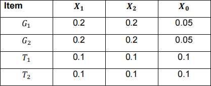
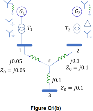
(b) For the power system shown in Figure Q1(b), the neutral of each generator is grounded with a reactance of 0.1 pu on a 100 MVA basis. The lines data and system data on a 100 MVA basis are shown on the network diagram and in the table below, respectively. For all the lines in this system, the positive and negative sequence impedances are equal and are shown on the diagram. The zero sequence impedances are also shown on the figure. The generators are running on no-load at their rated voltage and rated frequency.
For a balanced three-phase fault at bus 3 with a fault impedance of zf , the fault current magnitude is 3 pu. Determine the fault current for the following faults with the same fault impedance in all cases.
(i) A single line-to-ground fault at bus 3.
(ii) A line-to-line fault at bus 3.
(iii) A double line-to-ground fault at bus 3. Also calculate the phase currents in this case. [30%]
(c) A 50-Hz synchronous generator has a transient reactance of 0.2 per unit and an inertia constant of 4 MJ/MVA. The generator is connected to an infinite bus through a transformer and two parallel transmission lines, as shown in Figure Q1(c). Resistances are neglected and impedances are expressed on a common MVA base and are marked on the diagram. The generator is delivering a real power of 0.83 per unit to the infinite bus (Bus 1), when the terminal voltage of the machine (vt ) is 1.0 per unit. The infinite bus voltage is vbus = 1.0∠0° pu.
If a fault happens at the top transmission line at a distance of 30% of the line length from bus 2, determine the swing equation for this system.

[40%]
Question 2
(a) Discuss the technical and economic choices facing electricity companies looking to provide low-carbon electricity to communities, and improve reliability, security and efficiency (economic and energy) of the electric system. [40%]
(b) Consider the circuit shown in Figure Q2, in which a 33kV line (i.e. phase to phase) voltage three-phase power line connects a grid supply point to a load. The load is always at unity power factor, and consists of base load (unvarying) and flexible load (varying). The 33/11 kV transformer has an on-load tap changer that maintains the load voltage at 11 kV. You may assume that the phase RMS current I in a three-phase circuit with line voltage V and real power flow P at unity power factor is

(i) If the base load Lb is 1 MW throughout the day, calculate the daily energy loss on the 33 kV line due to the base load. [20%]
(ii) The flexible load Lf (unit MW) is a function of electricity price p (unit £/MWh) as given by the following expression:
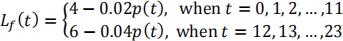
where the electricity price p(t) shall be positive, and t denotes the time for any hour in a day. Determine the levels of flexible load when p(t) = 50 fort = 0, 1, 2, … ,23, and calculate the daily energy loss on the 33 kV line due to both base load and flexible load. [20%]
(iii) If the electricity pricing scheme can be modified to p(t) = 40 fort = 0, 1, … ,11, and p(t) = 60 fort = 12, 13, … ,23, discuss the advantages of this electricity pricing scheme against the flat electricity pricing scheme of p(t) = 50 fort = 0, 1, 2, … ,23. [20%]
2023-08-08