DESIGN AND MANUFACTURE 2 (ENG2015)
Hello, dear friend, you can consult us at any time if you have any questions, add WeChat: daixieit
DESIGN AND MANUFACTURE 2 (ENG2015)
May 2016
Topic A: Limits and Fits (23 marks in total)
Referring to the BS4500 Table of selected fits for holes and shafts:
Q1. Choose the correct sizes of the maximum and minimum diameters for the code 30H9 in mm
a. 29.935 & 29.851
b. 30.025 & 30.000
c. 30.052 & 30.000 ***
d. 30.043 & 30.000
e. 30.062 & 30.000
[ 1]
This and subsequent similar questions test the students ability to read/use the BS4500 tables
Q2. Choose the correct sizes of the maximum and minimum diameters for the code 80H8 in mm
a. 80.300 & 80.000
b. 80.046 & 80.000 ***
c. 80.054 & 80.000
d. 80.000 & 79.965
e. 80.074 & 80.000
[ 1]
Q3. Choose the correct sizes of the maximum and minimum diameters for the code 120h6 in mm
a. 120.000 & 119.965
b. 120.000 & 119.981
c. 120.000 & 119.975
d. 120.047 & 120.012
e. 120.000 & 119.978***
[ 1]
Q4. Choose the correct sizes of the maximum and minimum diameters for the code 30g6 in mm
a. 29.991 & 29.975
b. 29.993 & 29.980 ***
c. 30.021 & 30.000
d. 29.986 & 29.961
e. 30.025 & 30.000
f. None of the above
Q5. Choose the correct sizes of the maximum and minimum diameters for the code 80f7 in mm
a. 79.970 & 79.929
b. 79.841 & 79.928
c. 79.866 & 79.940
d. 79.970 & 79.940***
e. 79.964 & 79.929
[ 1]
Q6. Choose the correct sizes of the maximum and minimum diameters for the code 120K7 in mm
a. 120.120 & 119.972
b. 120.100 & 119.975
c. 120.010 & 119.975***
d. 120.012 & 119.972
e. 120.025 & 120.003
[ 1]
Q7. Using your answers for Q1 and Q4 choose the kind offit you expect from the
code: 30H9g6
a. Ultra Tight
b. Transition
c. Clearance ***
d. Interference
e. Very Loose
f. None of the above
[1]
Q8. Using your answers for Q2 and Q5 choose the kind offit you expect from the
code: 80H8f7
a. Close
b. Transition
c. Interference
d. Transitory
e. Transfer
[ 1]
Q9. Using your answers for Q3 and Q6 choose the kind offit you expect from the
code: 120h6K7
a. Clearance
b. Over Clearance
c. Transition ***
d. Under Loose
e. Interference
[ 1]
Q10. Determine the upper deviation of the code 120K7 and also decide whether this code relates to a hole or a shaft, then choose the correct option from the choices
below:
a. -0.01 mm / hole ***
b. -0.012 mm / shaft
c. -0.025 mm / shaft
d. 120.100 / shaft
e. -0.025 mm / hole
[ 1]
Q11. Determine the lower deviation of the code 120h6 and also decide whether this code relates to a hole or a shaft, then choose the correct option from the choices
below:
a. -0.000 mm / shaft
b. -0.020 mm / shaft
c. -0.019 mm / hole mm
d. 0.012 mm / hole
e. 120.022 / shaft
[ 1]
Q12. Determine the fundamental deviation of the code 80f7, then choose the correct option from the choices below:
a. -0.071 mm
b. -0.003 mm
c. -0.060 mm
d. -30 microns***
e. -79.94 mm
[ 1]
Q13. Figure 1 shows a clutch hub connected to a shaft, at room temperature (20oC), the two parts create a fit 40h6P7 fit. The clutch hub is manufactured from cast iron
whereas the shaft is manufactured from stainless steel. Choose the kind offit that the clutch hub and shaft have at room temperature.
a. Clearance
b. Tranfer
c. Transition
d. Under Loose
e. Interference ***
[ 1]
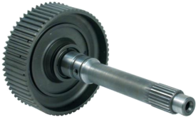
Figure 1.A clutch hub connected to a shaft.
Q14. Calculate the allowance of the 40h6P7 fit at the maximum material condition, in microns, then choose the correct value from the choices below:
a. - 1
b. 42
c. -60
d. -42 ***
e. -24
[2]
Allowance at MMC= min hole - max shaft = 39.958-40.000 = -0.042 mm = -42 microns
Q15. Calculate the allowance of the 40h6P7 fit at the least material condition, in microns, then choose the correct value from the choices below:
a. -42
b. - 1 ***
c. -0.042
d. 1
e. 60
f. None of the above
[2]
Allowance at MMC= Largest hole - smallest shaft = 39.983-39.984=-0.001mm = - 1 microns
Q16. The cast iron clutch hub and stainless steel shaft described in Q13 are heated
from room temperature to 50oC. The coefficients of linear thermal expansion of cast iron and stainless steel are 11.8x10⁻⁶ and 16.0x10⁻⁶ oC- 1 respectively. Calculate the
allowance between the two parts at 50oC for the maximum material condition, to the nearest micron.
a. -47 ***
b. -45
c. -63
d. -8
e. -29
f. None of the above
[3]
CTE = 11.8x10⁻⁶ and 16.0x10⁻⁶
Hole change and Shaft change = dT x L x alpha
Allowance = hole diameter -shaft diameter + hole change -shaft change Allowance = 39.958-40.000 + 39.958*30*11.8x10-6 – 40x30x16x10-6= -0.047054868
Q17. You should be able to derive the equation for the torque supported by an
interference fit. Derive the equation and then choose the correct equation from the following options.
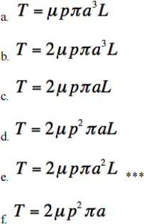
The students should be able to derive this equation. It’s a short and simple derivation so the question is worth 2 points. Alternatively they may have just memorised the
final equation.
Q18. After choosing the correct equation in Q16, decide which of the following options correctly defines the different symbols, as given in your lecture notes.
a. T = travel distance, p = density, a = diameter of the mating surface, L = length of the mating surface, μ = thermal expansivity
b. T = travel distance, p = interference pressure, a = diameter of the mating surface, L = length of the mating surface, μ = thermal expansivity
c. T = torque, p = interference pressure, a = radius of the mating surface, L = length of the mating surface, μ = coefficient of friction ***
d. T = torque, p = interference pressure, a = diameter of the mating surface, L = length of the mating surface, μ = coefficient of friction
e. T = torque, p = interference pressure, a = radius of the mating surface, L = diameter of mating surface, μ = coefficient of friction
f. T = torque, p = interference pressure, a = diameter of the mating surface, L = lubrication coefficient, μ = coefficient of friction
[1]
Topic B: Surface Texture and Tolerancing (16 marks in total)
Q19. Figure 2 show a device used for measuring some aspects of the geometry of a surface. Choose the correct statement:
a. Figure 2 shows an interferometer viewed under laser light, the surface could be perfectly flat
b. Figure 2 shows an optical flat viewed under monochromatic light, the surface could be perfectly flat ***
c. Figure 2 shows an interferometer viewed under monchromatic light, the surface could be concave
d. Figure 2 shows an optical flat viewed under monochromatic light, the surface could be concave
e. Figure 2 shows an optical flat viewed under monochromatic light, the surface could be convex
[ 1]

Figure 2. Device for measuring the geometry of a surface.
Q20. Figure 3 shows a representation of the surface roughness after apart has been machined using a lathe. Choose the correct meaning of the measurement length
shown in the image.

Figure 3. Surface texture after machining using a lathe.
a. Lay direction
b. Roughness height
c. Waviness height
d. Roughness spacing
e. Waviness spacing ***
[ 1]
Q21. Figure 4 shows a representation of the surface roughness after apart has been machined using a lathe. Choose the correct meaning of the measurement length
shown in the image.
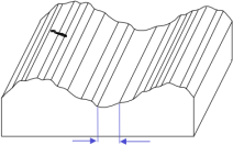
Figure 4. Surface texture after machining using a lathe.
a. Lay direction
b. Roughness height
c. Waviness height
d. Roughness spacing ***
e. Waviness spacing
[ 1]
Q22. Figure 5 shows a lay-symbol associated with a manufactured part. State the maximum centre-line average surface roughness of the part in microns.

Figure 5.A lay symbol.
a. 42
b. 0.005
c. 72 ***
d. 5
e. 10
f. 3
[1]
Q23. Again use Figure 5, this time state the maximum waviness height of the surface texture on the part in microns.
a. 42
b. 0.005
c. 72
d. 5
e. 10
[ 1]
Q24. Figure 6 shows a lay symbol for a shaft. Use Figure 7 to choose the best process to achieve both the minimum surface roughness of the shaft, as specified in the lay
symbol shown in Figure 6 and atolerance range of about 0.5mm.
a. Polishing
b. Sand casting
c. Rough milling ***
d. Broaching
e. Finish milling
[ 1]
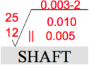
Figure 6.A lay symbol for a shaft.
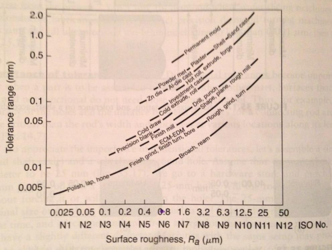
Figure 7.A graph showing tolerance range versus surface roughness attainable using a variety of manufacture processes.
Q25. Figure 8 shows the trace from a surface profilometer. Calculate the position of the datum (or centre) line, in microns, to within 1 decimal place.
a. 0.8
b. 0.9 ***
c. 1.0
d. 1.1
e. 1.2
[3]
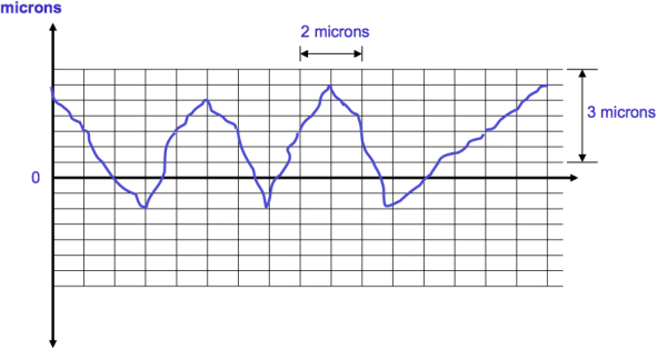
Figure 8. Surface profile produced using a surface profilometer.
This question takes a few minutes, the students must fine the approximate area above the and below the line by using triangles and then use the equation:
[(area above) – (area below)]/sample length = 0.92
Q26. Figure 9 shows the distribution of measured sizes of holes drilled into a steel plate. State the natural tolerance of the drilling process.
a. σ
b. 2σ
c. 3σ
d. 4σ
e. 5σ
[ 1]

Figure 9. Size distribution of holes drilled in a plate.
Q27. What percentage of the drilled holes do you expect to have a diameter within +/- 1σ of the average value?
a. 100%
b. 68.3% ***
c. 95.5%
d. 99.7%
e. 63.8%
[ 1]
Q28. You are told that the Process Capability Index for the manufacture of given
component, using a certain manufacture process is 1. The required tolerance when
manufacturing the component is 100 microns. Given that the size distribution of the parts manufactured using the process follows a normal distribution, state the value of the standard deviation in the size distribution of the parts.
a. 20 microns
b. 16.7 microns***
c. 100 microns
d. 1 micron
e. 25 microns
[2]
Students must know the equation PCI=Tolerance/6σ, they then just need to substitute in the values and rearrange to find σ=100/6= 16.7microns
Q29. Figure 10 shows a very basic representation of a device designed to measure surface roughness using laser light of 660nm wavelength. Bright light is seen at the top of the surface asperity. In terms of the number of wavelengths, what extra
distance would you expect one of the laser beams to travel if the bottom of the asperity was imaged, and state whether this would produce a light or dark spot?
a. n=6 therefore it would be light
b. n=6 therefore it would be dark
c. n=7 therefore it would be light
d. n=7 therefore it would be dark
e. n=5 therefore it would be light
[3]
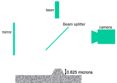
Figure 10.A device designed to measure surface roughness.
Students need to remember the equation n=dxdiff/wavelength and then do some
simple algebra. If they understand the operating principle they should realise that
when n is odd have destructive interference (brightness), if n is even get constructive interference (light).
Topic C: Materials Selection (17 marks in total)
Selection Problem 1
You are asked to select the best material to manufacture the cheapest panel of
specified length,L, that is both stiff enough to resist deflecting beyond a given
amount, 。, and strong enough not to break when subject to a given load, F. You are also told that the panel must have a minimum value for its thermal and electrical
conductivities.
Q30. Choose the number of objectives involved in Selection Problem 1 a. 0
b. 1 ***
c. 2
d. 3
e. 4
[ 1]
Q31. Choose the number of constraints involved in Selection Problem 1 a. 0
b. 1
c. 2
d. 3
e. 5
[ 1]
there are 4 so no correct answer given
Q32. Choose the number of material indices you would expect to find in Selection Problem 1
a. 0
b. 1 ***
c. 2
d. 3
e. 4
[ 1]
Q33. If the cross-sectional area, A, of a tie is 2500mm2, the length of the tie, L, is
15cm, the density, p, of the material in the tie is 7000kgm-3 and the cost per kg of the material is £0.50. Calculate the cost of the tie:
a. £1.92
b. £1.03
c. £0.50
d. £1.31***
e. £2.63
f. None of the above
[2]
They need to know the following equation to answer this question: m = ALP and they have to be careful with the units.
Selection Problem 2
You are asked to select the best material to manufacture the lightest possible piston connection rod for an internal combustion engine. The connection rod is designed to transmit a compressive load from the piston to the engine. It must not buckle due to the compressive load or fail due to fatigue. A diagram of the rod, showing symbols indicating the force and the main dimensions of the connection rod is given in Figure 11. Note the rod has a rectangular cross- section.

Figure 11. Schematic of apiston connection rod showing force, F, and the main dimensions of the rod.
Q34. According to the systematicselection procedure discussed in this course, what is the objective in Selection Problem 2?
a. to minimise density
b. to minimise cross-sectional area
c. to maximise strength
d. to maximise stiffness
e. to minimise mass ***
[ 1]
Q35. According to the systematicselection procedure discussed in this course, what are the free variables in Selection Problem 2?
a. density and cross-sectional area
b. cross-sectional area and mass
c. material and cross-sectional area ***
d. material and density
e. mass and material
f. None of the above combinations are fully correct
Q36. Still referring to Selection Problem 2, you are asked to write down the mass, m, of the connection rodin terms of the; cross-sectional area, A = b × w, density, P and length, L. Choose the correct equation and the meaning of the symbol, β .
a. m = AβPL where β is a factor to account for the extra mass of the bearing houses ***
b. m = A2 βPL where β is a factor to account for the stress concentration in the bearing houses
c. m = AβPL2 where β is a factor to account for the extra mass of the bearing houses
d. m = ![]() where β is a factor to account for the stress concentration in the bearing houses
where β is a factor to account for the stress concentration in the bearing houses
e. m = AβPL where β is a factor to account for the stress concentration in the bearing houses
f. m = A2βPL where β is a factor to account for the extra mass of the bearing
[2]
Q37. Selection Problem 2 suggests that the rod should be designed to resist
failure due to fatigue. Given that the endurance limit of the material is given as σe, choose the equation that correctly embodies this requirement.
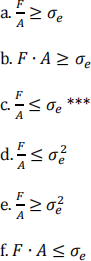
[1]
Q38. Using the equations you chose in Questions 36 & 37, eliminate the cross- sectional area, A, in order to find an equation for the lightest connection rod, of mass, m1, that will not fail due to fatigue. Arrange the resulting equation such that it contains a material index enclosed in a bracket. Select the resulting,
correctly formatted equation, from the list given below:
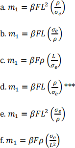
[2]
Some effort and algebra is required in this question and students must be able to recognise the material index
Q39. Selection Problem 2 also states that the rod should be designed to resist
failure due to compressive buckling. From structural mechanics we know that, in order to prevent buckling the compressive force must not exceed the Euler
buckling load, i.e.,

where I = b3w⁄12. In order to include the cross-sectional area, A, in this
equation we can write the beam thickness in terms of its width as b = aw, where a is a dimensionless constant. Using this information, derive an expression for
the cross-sectional area of the connection rodin terms of the compressive force, F, the rod length, L, the Young’s modulus, E and a, next choose the correct
expression from the following choices:
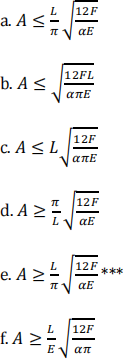
[3]
the solution is given below, the student just needs to do some algebra, they are familiar with this problem from their lectures.
![]()
![]()
![]()
![]()
![]()

derivation required for Q39
Q40. Still referring to Selection Problem 2, combine the equation you selected in Q36 for the mass of the component, with the equation you selected in Q39 to eliminate the cross-sectional area, A, and derive the minimum mass, m2, of a rod that is able to withstand the buckling load, F. This time, you don’tneed to arrange the resulting equation such that it contains a material index enclosed in a bracket. Select the correct equation from the choices given below:

2023-08-07