ENGR202 Instrumentation and Control EXAMINATIONS 2019
Hello, dear friend, you can consult us at any time if you have any questions, add WeChat: daixieit
EXAMINATIONS 2019
PART II (Second Year)
ENGINEERING
Paper 2 (3 hours)
Instrumentation and Control (ENGR202)
SECTION A INSTRUMENTATION - Answer TWO questions from this section
A1 Answer ALL parts (a) - (d)

Shown in Figure A1-1 is a schematic diagram of an inductance-based accelerometer. The following information is available:
o Coil length: 20 mm
o Coil inductance when rod fully withdrawn: 2 μH
o Coil inductance when rod fully inserted: 10 μH
o Spring constant: 20 N m-1
o Mass of ‘mass’ plus rod: 20 grams
o Coil inductance when device at rest: 6μH
(a) Determine the maximum acceleration that can be read with this device. (7 marks)
(b) Design an alternative capacitance-based accelerometer transducer. Your answer should include a diagram along with any equations you think are relevant. (6 marks)
(c) Name 6 technical considerations you might look at when designing or buying an accelerometer. (6 marks)
(d) Describe three applications where youraccelerometer design in part (b) could be used. (6 marks)
A2 Answer ALL parts (a) - (c)
(a) Describe how the following temperature transducers work:
o Optical pyrometer (3 marks)
o Platinum Resistance Thermometer (PRT) (3 marks)
o Thermocouple (3 marks)
o Gas thermometer (3 marks)
(b) A temperature measuring application requires the use of either a
thermocouple or a platinum resistance thermometer. State one advantage of using a thermocouple and one advantage of selecting a platinum resistance thermometer. (2 marks)
(c) A gas thermometer (Figure A2-1) is to be used to measure the temperature in a pressurised balloon of air. The whole experiment is being undertaken in a laboratory at an altitude of 1,000 m above sea level.
2 cm
![]()

|
Additional information: |
o Pressure at sea level: 101,325 Pa
o Mercury Density: 13,534 g L-1
o Gas Constant, R: 8.3145 J K-1 mol-1
o Volume of gas in balloon: 12.2 L
o Number of moles of gas in the balloon: 0.5
o Temperature in Lab: 290 K
o Pℎ = P0 e −0.000115∗ℎ where his height in metres
Calculate the following values:
(i) The air pressure within the laboratory. (3 marks)
(ii) The pressure of the air in the balloon. (4 marks)
(iii) The temperature of the gas in the balloon. (4 marks)
(Note: if you cannot answer part (i), then take the ambient pressure in the lab to be 90,000 Pa. Similarly, if you cannot get a figure for part (ii), then use a value of 105,000 Pa for the pressure within the balloon.)
A3 Answer ALL parts (a) - (c)
You are tasked with the design of a cheap rheometer system to determine the viscosity of a liquid over a period of an hour as water is slowly added.
(a) Draw a diagram of your viscosity meter transducer with clear indication of how the device works and the output that it will produce. Indicate which proportionality constants will be needed in your system. (8 marks)
(b) The next stage is to design some signal processing instrumentation to convert this transducer output signal into a format suitable for the analog input pin of a Data Acquisition (DAQ) system or microcontroller. Draw diagrams to
illustrate how your instrumentation will convert the transducer output signal to a suitable format, amplify the signal and filter out any noise. (12 marks)
(c) Once your signal has gone through signal processing, one way to read the
signal is via a microcontroller. Assuming you have connected the processed signal from part (b) into the analog input pin A0, and a ground pin – write the pseudo-code you would use to take the value in and write it to screen. Be sure to state any assumptions you have made in your answer. (5 marks)
![]() SECTION B CONTROL - Answer TWO questions from this section
SECTION B CONTROL - Answer TWO questions from this section
B1 Answer ALL parts (a) - (e)
In this question, the differential equation of an uncontrolled system is given by the following mathematical model:
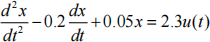
where x(t) and u(t) are the output and input, respectively.
(a) Determine the Transfer Function form of the uncontrolled system and hence
show that the characteristic equation is given by s2 - 0.2s+ 0.05 = 0 . (3 marks)
(b) Using the characteristic equation stated in part (a), determine the poles of the uncontrolled system and the stability condition, and sketch the general form of the time response. (3 marks)
(c) Draw the block diagram of a proportional-derivative (PD) control system, as applied to the Transfer Function determined in part (a). Hint: expressed as a
Transfer Function, the PD controller takes the following standard form:
U(s) = (KP + KDs)(V(s) - X(s))
where V(s) represents the set point. (3 marks)
(d) For the control system in part (c), design a PD controller (i.e. determine values of KD and KP ) such that the closed-loop damping ratio ζ = 1.1 and the
natural frequency Φn = 0.3 rad/s. Hint: the general form of the characteristic equation for a second order system is: s2 + 2ζΦns + Φn 2 = 0 . What is the significance of designing this controller such that ζ 之1? (12 marks)
(e) What are the potential disadvantages of the PD control system selected above? Suggest alternatives, explaining the reasons for your answer. (4 marks)
B2 Answer ALL parts (a) - (e)
Consider the following Transfer Function model derived for an air conditioning unit:
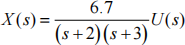
where X(s) and U(s) represent the outlet and inlet temperature, respectively.
(a) Write down the characteristic equation of the model. Determine the poles,
stability condition and steady state gain of the model. Plot the position of the poles on the complex s-plane. For a unit step input of 20° C, what is the steady state outlet temperature? Comment on the physical interpretation of all these results. (7 marks)
(b) Briefly explain what is meant by the frequency response of a system. (3 marks)
(c) Using standard notation from the lectures, and noting that M = ![]() G(s) s
G(s) s![]() =j负 and Q = Arg (G(s)) s
=j负 and Q = Arg (G(s)) s![]() =j负 , determine the frequency response of the air conditioning unit Transfer Function model i.e. derive expressions that show how M and Q vary with 负 . (6 marks)
=j负 , determine the frequency response of the air conditioning unit Transfer Function model i.e. derive expressions that show how M and Q vary with 负 . (6 marks)
(d) Using a carefully annotated sketch, including axis labels, explain how a
Nyquist Diagram can be used to determine the stability of a system. Your
sketch should show appropriate traces for (i) atypical stable and (ii) unstable system. Your written answer should briefly explain what is plotted in the
Nyquist Diagram. Hint: the sketch is an approximate graph drawn in your answer book and does not require graph paper nor use of the equations derived in part (c). (5 marks)
(e) Explain how the frequency response can be used to analyse and set design criteria for the stability of a closed-loop control system. (4 marks)
B3 Answer ALL parts (a) - (d)

(a) In the generalised first order model, what are the names of the variables τ and K? For the first order model with K = 5 and a steady input of 2 units, determine the value of x(t 喻伪) . For the second order model, sketch the time response mode if ζ = 0 and explain the physical significance of this result. (5 marks)
(b) For the tank system shown in Figure B3- 1, derive an ordinary differential
equation expressing the outflow rate Qo , as a function of the inflow rate Qi and area A. You may assume that Qo is proportional to the head of water h. List any other assumptions you have made to develop this model. Convert the model into the generalised first order form. Determine the steady state gain and comment on the physical significance of this result. (5 marks)
(c) For the LC circuit shown in Figure B3-2, derive a model expressing the voltage Vo(t) in terms of L, C and the applied voltage Vi(t) . List the assumptions you have made. Convert the model into a generalised second order form.
Determine the forcing function, output, damping ratio and natural frequency of the model. (7 marks)
(d) Using the LC circuit as an example, explain what is meant by the following
terms: (i) linear system; (ii) mechanistic model; (iii) open-loop system. Briefly explain how generalised model forms can be useful when analysing dynamic systems. (8 marks)
2023-08-05