CIV3294: Structural Design
Hello, dear friend, you can consult us at any time if you have any questions, add WeChat: daixieit
CIV3294: Structural Design
Question 1
A universal column 100UC14.8 of Grade 300PLUS is under combined compression force N* =100 kN and bending moment (Mx *) about is major x-axis. The bending moment Mx * is the product of N* and the load eccentricity (e) which is 150mm. The column length L=5000 mm. The effective length factor ke=1.0 and section constant ab= 0. Assume FLR is provided.
Calculate the design column section capacity about x-axis (φNsx), design column member capacity about x-axis (φNcx), and design bending moment capacity about x-axis (φMsx).
Is the universal column 100UC14.8 of Grade 300PLUS adequate under the combined action? If yes, how much can you increase the load eccentricity (e) before the failure of the column occurs? If no, how much should you reduce the the load eccentricity (e) to avoid the failure of the column?
Question 2
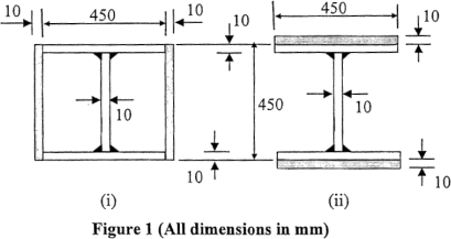
A Grade 300, lightly welded (LW) steel I-section is to be strengthened by light welding two plates of 450 mm 10mm to the section. Two possible positions are considered as shown in Figure 1 (i) and (ii).
Question 3
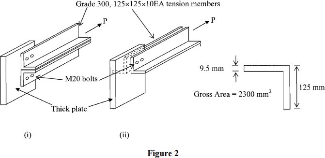
A thick steel plate is connected to a pair of Grade 300, 125× 125× 10EA (equal angle) section through a line of M20 bolts as shown in Figure 2. The pair of equal angles is subjected to total tensile force P in kN. The connection can be arranged so that the angles are one side of the thick plate as in Figure 2 (i) or on both sides as in Figure 2 (ii). A cross-section of the equal angle section is also shown in Figure 2.
Determine the maximum force P that the angles can take for each of the cases shown in Figures 2 (i) and (ii).
Question 4
A tension member made of hot-rolled parallel flange channel (PFC) carrying a design tensile force of 300 kN is connected to a column through a gusset plate as shown in Figure 3. The angle between the PFC and horizontal axis is assumed to be 600.
(a) Determine the minimum size of a Grade 300 PFC section required for the tension member.
(b) Determine the minimum number of M20- 8.8/S bolts required for the connection by checking shear only. Assume threads of bolt intercepting the shear plane. Spacing between the bolts is less than 300 mm. (Note: the number of bolts shown in the diagram may be changed).
(c) Determine the minimum size of the weld required for connecting the gusset plate to the column. Use E48XX rodand SP welds, and assume the cross-section of the gusset plate is 180 mm× 45mm.

Question 5
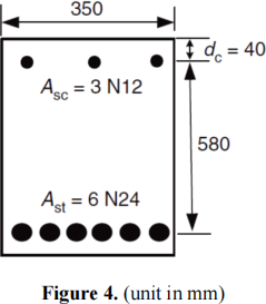
Given a reinforced beam section as shown in Fig. 4, calculate the maximum design bending moment (You do not need to check pmin). The compressive strength of concrete fc’=32 MPa, steel yielding strength fsy = 500 MPa and steel modulus Es = 200 GPa. Take nominal area = 450 mm2 for each N24 bar and 110 mm2 for each N12 bar.
Question 6
A short reinforced concrete column with a section shown in Fig. 5 is subjected to axial compression and bending about they-y axis (two bars at top are in compression while four bars at bottom are in tension). Calculate the ultimate axial force capacity Nu and bending moment capacity Mu at points A and C in the capacity line. Take the concrete compressive strength f’c = 32 MPa, yield stress of steel fsy = 550 MPa and steel modulus Es = 200,000 MPa. All bars are Y28 with a nominal area = 620 mm2 each.

Question 7
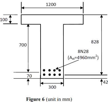
The reinforced concrete beam shown in Figure 6 is to carry a factored design shear force V* = 550 kN. Check if the section dimensions are adequate for shear and if more than minimum shear reinforcement is required at the most critical section for shear. If yes, calculate the required spacing of Y12 stirrups (two legs with a total area of 220 mm2) at the most critical section for shear. Assume angle of compression strut θv = 45o. Take overall depth D = 870 mm, Ast = 4960 mm2, effective web width bv = 300 mm, concrete compressive strength f’c = 20 MPa, and steel yielding strength fsy,f = 500 MPa.
Question 8
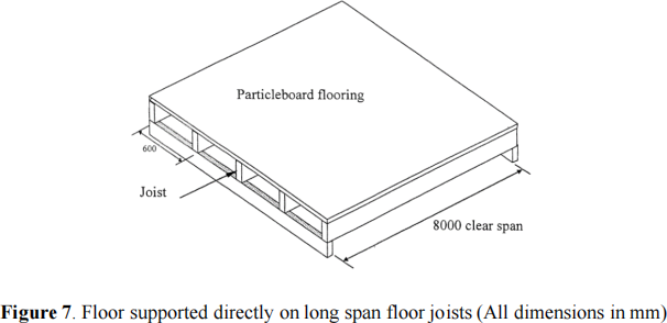
Timber floor joists are used to support a floor in an office building (office for general use) as shown in Figure 7. The joists are simply supported over a span of 8 m, are spaced at 600 mm centres and support 25 mm thick plasterboard flooring. Assume that the Swan timber is available in depth increments of 33 mm (eg, 300, 333, 367, 400mm, etc) and widths of either 80 or 100 mm. Take the density of plasterboard and the swan as being 650 kg/m3.
Select a suitable F grade section capable of supporting the load. You must check all relevant load combinations for strength and serviceability.
Question 9
You have been asked to design a new sports building to be located within the Monash University Sports and Recreation Centre. The new building has a hall which will be used to hold concerts, indoor sports events, and large public meetings. Your task is to design the floor joists beneath the hall. The structural layout of the floor is shown in Figure 8. The floor joists will consist of:
. 175 mm×50 mm swan, seasoned, visually graded F17 timber beams. Unit weight of the timber joists is 6.0 kN/m3.
. Unit weight of the compressed chipboard floor acting on the joists is 0.3kN/m3. In this case, assume that the floor fully restrains the joists from lateral buckling and that bending only occurs about the major axis. Assume the thickness of the chipboard floor is 25mm.
. The simply supported design span is 2.5 metres. The distance (centre to centre) between adjacent joists is 0.6 metres.
The architect has made some specific requests:
. The joists need sufficient capacity to withstand an imposed (5 hours) crowd loading of 5kPa.
. Deflection of the joists shall not exceed 30 mm.
(a) Do the joists have sufficient bending capacity? i.e. -verify that the design bending capacity, is greater than the factors design moment, M*. In your calculation, you must check all relevant load combinations for bending strength.
(b) Calculate the deflection of a floor joist at mid-span for permanent and imposed loading. Do the joists comply with the specific limit of 30mm? In your calculations, assume E=14,000 MPa.

Question 10
Consider the wall which is at the ground floor level of an apartment building with a tiled roof and supports two higher concrete slabs (Fig. 9). The factored load on the top of the ground floor wallis 170 kN per metre comprising 100 kN/m from above and 70 kN/m from the first floorslab. The ground floorslabis on fill and isolated from the wall. The wall material is clay masonry, fully bedded with M3 mortar (noraking) and the brick strength is f’uc of 20 MPa.
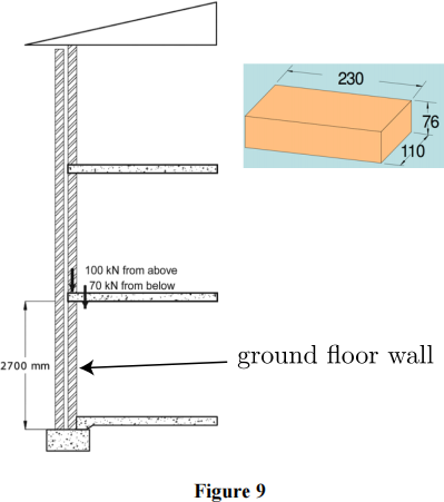
(i) Calculating the basic compressive capacity F0.
(ii) Calculating the design compressive force Fd acting on the ground floor wall. (iii)Using the simple rules, check the design Fd < kF0.
(iv)Using the refined rules, check the design
(a) Calculating the eccentricities e1 given that the other eccentricity is zero. (b) Calculating Sr and k.
(c) Compare the results of simple rules and refined rules.
Question 11
An unreinforced double-leaf clay brick wallis 3000 mm high and 2000 mm long. It is supported at top and bottom. The clay bricks (230x110x76 mm) have characteristic compressive strength of 20 MPa. The wallis bonded with 10 mm thick M2 mortar in unraked joints (i.e.full bedded). The wallis subjected to uniform wind pressure 0.5 kPa. Assume the characteristic flexural tensile strength of masonry,f’mt = 0.2 MPa. Calculate the vertical bending moment capacity of the wall and check with the design capacity.
2023-08-05