ENGR202 Instrumentation and Control EXAMINATIONS 2018
Hello, dear friend, you can consult us at any time if you have any questions, add WeChat: daixieit
EXAMINATIONS 2018
PART II (Second Year)
ENGINEERING
Paper 2 (3 hours)
Instrumentation and Control (ENGR202)
![]()
![]() SECTION A CONTROL - Answer TWO questions from this section
SECTION A CONTROL - Answer TWO questions from this section
A1 Answer ALL parts (a) - (e)
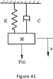
(a) For the mass–spring–damper system shown in Figure A1, derive a linear time invariant mathematical model expressing the displacement x as a function of the mass M, spring stiffness K and damping parameter C, when an external force F(t) is applied to the mass. List the assumptions you have made. (3 marks)
(b) Put the mass–spring–damper model into the standard second order form shown below. Find the steady state gain, damping ratio, natural frequency and forcing function.
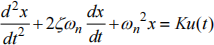 (5 marks)
(c) Sketch the response of the mass–spring–damper system for the case that
C = 0 and explain the significance of this result. On the same plot, sketch the response of a critically damped system. For the case that M = K = 1, determine the value of C that yields a critically damped system. (5 marks)
(d) The following differential equation represents the closed-loop dynamics of a proportional-velocity (PV) control system:
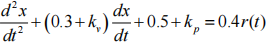
where x is the output and r(t) is the set point, while kv and kp are control gains. Design a controller (i.e. determine the values of the control gains) that yields closed-loop damping ζ = 1 and Φn = 1.2 rads/s. Find the steady state gain of the closed-loop system, and state whether or not this control system achieves steady state tracking of the set point. (6 marks)
(e) With the aid of sketches and/or any of the equations and analysis considered above, discuss the strengths and weaknesses of PV control in comparison to proportional-integral (PI) control. (6 marks)
A2 Answer ALL parts (a) - (d)
(a) Consider one of the joints of a robotic manipulator, for which the joint angle and an applied voltage represent the output and input respectively.
(i) Define the terms open– loop and closed– loop control, using the robotic manipulator as an example. (3 marks)
(ii) Briefly explain the term stability. What are the likely practical consequences of using an unstable robotic manipulator control system? (3 marks)
(iii) Using the robotic manipulator as an example, explain the term dead-zone nonlinearity. (2 marks)
(b) A simplified model for the robotic manipulator (without control) is as follows:

where x is the joint angle and u(t) is the input. Determine the Transfer Function form of this model. Find the pole, plot its position on the complex plane and state the stability condition. Write down an expression for how to determine the steady state gain of this model, and comment on the physical interpretation of your answer. (6 marks)
(c) State the stability condition of the following characteristic equations, giving the reason for your answer in each case.
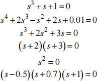 (3 marks)
(d) Figure A2 shows a Proportional– Integral (PI) control system.

(i) Is the proportional gain k1 or k2 ? (1 mark)
(ii) Using algebra or the rules of block diagram manipulation, show that the Closed Loop Transfer Function is
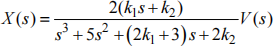 (4 marks)
(iii) Find the steady state gain of the Closed Loop Transfer Function and comment on the significance of your answer. (3 marks)
A3 Answer ALL parts (a) - (d)
The following information is provided for this question:
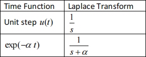
The frequency response of a Transfer Function G(s) is given by:

(a) Draw a block diagram of a generalized control system, in which H(s) is the model, C(s) is the control algorithm and F(s) is a feedback element. On
your diagram, label the set point V(s), control input U(s) and output X(s) . (2 marks)
(b) Using either standard algebra or the rules of block diagram manipulation,
determine the Closed Loop Transfer Function and write down the associated characteristic equation. (4 marks)
(c) List and explain, with examples of your own choice, the four common
objectives of control system design as considered in the course. Where
relevant, support your answer with the block diagram from part (a) and the Transfer Function from part (b). (9 marks)
(d) Consider the model: 
(i) Using the Laplace transforms stated above, determine the unit step response of the model. (5 marks)
(ii) Determine the frequency response of the model i.e. the magnitude M and phase φ . (5 marks)
SECTION B INSTRUMENTATION - Answer TWO questions from this section
B1 Answer ALL parts (a) - (c)
(a) A lambda probe typically has four wires coming out of it. What is the typical function of these wires? (4 marks)
(b) You wish to utilize the Beer Lambert law to determine the level of methane in a room over the course of a day. Design a system to do this, showing in your answer:
(i) The sensor type you will use and where it will be located. (2 marks)
(ii) Any other experimental apparatus needed. (2 marks)
(iii) Any signal processing your sensor signal will encounter. (2 marks)
(iv) Any calculations needed to determine the concentration of the gas. (2 marks)
(v) How the user will observe the concentration. (2 marks)
(c) Beta radiation is incident on a large ionization chamber type detector with a fill gas of argon. The following information about the detector and source are available.
. Source = Caesium-137
. Energy of Beta Radiation = 512 keV
. Dimensions of detector = 1 m3
. Cross section = 30 barns
. Density of argon: 1.78 g/l
. Atomic weight of argon: 39 amu
. Mass of 1 amu: 1.66x10⁻²⁷ kg
. Temperature of gas in detector: 300 K
(i) What is the number density of the argon? (5 marks)
(ii) What percentage of the beta radiation will be detected in this instrument? (6 marks)
B2 Answer ALL parts (a) - (d)
(a) Describe how a capacitive humidity sensor works with use of a diagram. (5 marks)
(b) A certain polymeric dielectric possesses a relative permittivity of 3 when there is 0% humidity, linearly rising to a value of 10 when there is a humidity of 100%. A capacitive humidity sensor is made using this dielectric. Furthermore, another similar structure with the same dimensions as the humidity sensor but with a fixed dielectric constant is constructed. These two are placed in a bridge circuit as shown in Figure B2.

Assuming that R3=R4, Vs=5 V and the only difference between Csensor and Cfixed is that the dielectric constant varies in the sensor, determine a relationship between Vo and Vs (in terms of the humidity), simplifying the resultant equation as much as possible. (9 marks)
(c) The output signal from the humidity sensor is too small to provide accurate results all of the time. Measurements indicate that the Signal to Noise ratio (SNR) is around 1 for most of the time that the sensor is operational. What does a SNR of 1 mean? (3 marks)
(d) Define what the following eight terms mean when discussing sensors. Also, list another four terms which you feel are relevant to the design of sensors.
. Sensitivity
. Accuracy/Uncertainty
. Resolution
. Noise equivalent power (NEP)
. Hysteresis
. Long term instability
. Short term instability
. Calibration
(8 marks)
B3 Answer ALL parts (a) - (d)
Modern speedometers in cars utilize magnets and magnetic field sensors such as Hall sensors.
(a) Describe, with use of a diagram, how a Hall effect sensor works. (6 marks)
(b) A client wants your engineering firm to design a system that detects the level of fuel in a tank, by floating a magnet on the top of the fuel, with a fixed Hall sensor at the top of the tank. What is the minimum Hall voltage produced by
the system (i.e. when the magnet is at the bottom of the empty tank)?
Supplementary information:
. Magnetic field when magnet is at bottom of tank: 0.15 T
. Hall sensor material: Copper
. Density of Copper: 8.96 g/cm3
. Copper thickness: 100 μm
. Temperature: 300 K
. Copper charge density: 8.47x1028 electrons/m3
. Current passed through sensor: 100 mA
(6 marks)
(c) Another use of Hall sensors is in a speedometer for a car. A design submitted by a colleague involves 4 magnets distributed evenly around the outside of a car axle. Considering the following information and the Nyquist theorem, calculate the sampling frequency that your microcontroller must have, in order to detect over the full range of car speed.
. Friction co-efficient: 0.7
. Car tyre diameter: 80 cm
. Car maximum speed: 160 km/hr
. Engine displacement: 2.0 Litres
(6 Marks)
(d) Design an alternative way to determine the speed of the car, using any of the techniques you have covered within this course. Your design should clearly show how the system will work e.g. for the benefit of any technician who might eventually try and bring your design to life. (7 marks)
2023-08-05