FEEG2002W1 MECHANICS, MACHINES AND VIBRATION SEMESTER 2 EXAMINATIONS 2021-22
Hello, dear friend, you can consult us at any time if you have any questions, add WeChat: daixieit
FEEG2002W1
SEMESTER 2 EXAMINATIONS 2021-22
TITLE: MECHANICS, MACHINES AND VIBRATION
Q.1.
(i) In Figure 1.a., the crank AD, rotating about fixed axis A, has a pin D which slides in the straight slot of link CE. Link BC turns about
joint B.
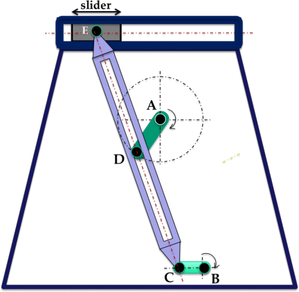
Figure 1.a. Linkage Mechanism
Using Grubler’s formula, calculate the mobility of this mechanism and state any assumptions that you make. [5 marks]
(ii) In the quick-return, crank-rocker planar mechanism, shown in Figure 1.b., the crank rotates at a constant angular velocity of 200 rad/s in the clockwise direction.
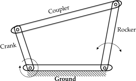
Figure 1.b. A crank-rocker mechanism
For the position corresponding to the maximum transmission angle, draw the velocity and acceleration diagrams and determine the following:
a) Velocities (magnitudes and directions) of all the joints, [10 marks]
b) Angular velocity of the coupler and the rocker, [2 marks]
c) Centripetal accelerations of all of the joints, [3 marks]
d) Magnitude and direction of the acceleration of the coupler-rocker joint with respect to the frame, and [8 marks]
e) Magnitude and direction of the acceleration of the coupler-rocker joint with respect to the crank-coupler joint. [2 marks]
f) Calculate the time ratio for this mechanism. [3 marks]
The lengths of the links are:
Crank = 25 mm,
Coupler = 100 mm,
Rocker = 50 mm,
Ground = 90 mm.
TOTAL [33 MARKS]
Q.2.
A lumped parameter single degree of freedom model representing a workshop lathe of mass m equal to 500 kg supported on an elastic undamped linear elastic spring support of stiffness k, equal to 100 kNm-1 , is shown in Figure 2. The foundation of the workshop experiences vertical vibration due to a nearby railway line and the isolation design has end stops such that the spring cannot be compressed dynamically by more than 5 cm from its static equilibrium
length.
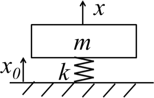
Figure 2. Isolated machine undergoing base excitation due to workshop floor vibration.
(i) Draw the separate Free Body Diagrams for the vertical dynamic forces acting on the machine mass m and the isolation stiffness k from the static equilibrium position when base motion x0 (t) is present, i.e. you do not need to include the weight of the machine, and the machine has a dynamic displacement x (t) . [4 marks]
(ii) For harmonic vertical base displacement x0(t) = X0ejwt obtain an expression for the steady state compression z(t) = zejwt = x0(t) 一 x(t) of the spring and hence an expression for the frequency response function (FRF) x0/Z 0 between the compression and the base input displacement. [6 marks]
(iii) On log-log scales, sketch the variation of the magnitude and phase of the compression Z as a function of frequency 幼. Clearly indicate the important features on the sketches. [6 marks]
(iv) Identify the value of viscous damping ratio necessary to add to the isolation system to avoid the isolation design limit being exceeded when the base displacement has an amplitude of 1 cm and the excitation is at the natural frequency of the undamped system. [8 marks]
(v) When trains are not running, i.e. no base motion x0(t) = 0, the machine foundation is assumed rigid. The lathe operates at a rotational speed up to 2000 rpm and machines an item of mass 5 kg. The mass is unbalanced on the shaft of the lathe and it can be considered as behaving as an eccentric mass with an eccentricity of 5 mm from the nominal mass centre of the lathe. Check if the system will be at resonance over the given operating speeds for the machine and determine whether the springs will bottom out, i.e. be fully compressed, assuming that the damping is still in place and equal to the value selected for part (iv). Quote any relevant formulae and assumptions used. [6 marks]
(vi) The spring mounts are replaced by stiffer springs having the same compression limits. Explain if the dynamic compression of the stiffer springs at resonance, for the same base amplitude motion, would either increase or decrease under the background train vibration base excitation when all the other physical parameters are unaltered. [3 marks]
TOTAL [33 MARKS]
Q.3.
A television screen is modelled at low frequencies in the vertical plane as a uniform rigid beam of mass M supported at its upper end P, where it is restrained by a very stiff vertical elastic spring KV and a horizontal elastic spring of stiffness KH. At the lower end further restraint is provided by another horizontal elastic spring of stiffness 2KH. The screen is of length 2L and the moment of inertia about the
centre of mass C is equal to J (see Figure 3). Under low amplitude vibration, the vertical motion of the screen is negligible and can be ignored and the motion is to be analysed using the two degrees of freedom namely the translation y of the centre of mass and rotation ![]() about the centre of mass.
about the centre of mass.
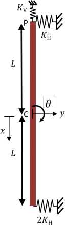
Figure 3. Television screen with horizontal translation and rotation about centre of mass C
The natural frequencies for the installed screen are 1.28 Hz (mode 1) and 2.81 Hz (mode 2) and the corresponding scaled mode shapes are given as columns in Table 1.
|
|
Mode 1 |
Mode 2 |
|
Translation (y) |
1.0 |
-0.3183 |
|
Rotation ( |
0.1415 |
1.0 |
(i)
(a) Using Lagrange’s equations of motion, or otherwise, obtain the matrix form for the equations of motion in the translation y and
rotation ![]() degrees of freedom. [11 marks]
degrees of freedom. [11 marks]
(b) For a screen of total length 2L = 6 m, show that the modes are orthogonal with respect to the stiffness matrix, i.e. within rounding errors the numerical value is a small factor of the elastic stiffness KH. [3 marks]
(c) Determine the pivot point, or equivalently the nodal point, for the fundamental mode and sketch this mode. [4 marks]
(d) To reduce the vibration a viscous damper of viscous damping constant c can be applied to act in parallel with the upper spring. Show why a modal solution of a forced vibration problem is inappropriate for this system. [5 marks]
(ii) Concern is raised that the screen is vibrating in its fundamental flexural mode and the fundamental natural frequency is to be estimated using Rayleigh’s Method. Use a shape function for the deflection of the screen y (x, t ) = φ(x )sin ωt for −L ≤ x ≤ L , where φ(x ) = (x − 2L)2 . The screen has bending stiffness EI and mass per unit length ρA.
(a) Show that the function is suitable to use, and
(b) showing each step in your analysis/algebra, that the fundamental natural frequency estimate ω0 , in rad/s, is
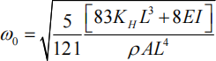
[10 marks]
[TOTAL 33 marks]
2023-07-26