CAN102 Electromagnetism and Electromechanics Lab 2
Hello, dear friend, you can consult us at any time if you have any questions, add WeChat: daixieit
CAN102 Electromagnetism and Electromechanics
Lab 2 Single-phase Transformers
General Information
Operating instructions
(1) Be familiar with equipment used and understand the functions;
(2) Work in groups of 3 people;
(3) Make wiring according to the connection diagrams;
(4) Observe the instruments after switching on the equipment, if there is any abnormal operation or smell, switch off the power immediately and identify the fault;
(5) Measure parameters according to the operating instructions;
(6) Turn off the power supply system when finished a set of measurements, then continue to the next step.
Safety Instructions
(1) Never touch a live circuit.
(2) Only connect or disconnect wires with the power switched off.
(3) Turn on the power supply with instructor’s permission, and switch off the power immediately if a fault occurs.
(4) Check the power meter and ammeter before switching on the power, a short-circuit fault must be avoided.
(5) The main power switch should be operated with instructor’s permission.
1. Objectives
To measure the transformation ratio and parameters of a single-phase transformer.
2. Pre-lab
2.1 What are the features of no load and short circuit tests of a transformer, respectively? To which side should the power supply be connected during each test and why?
2.2 How should the instruments be connected to avoid measurement errors during no load and short circuit tests? How should the wattmeter W be connected to a circuit?
3. Laboratory exercises
3.1 No load test
Measure the no load characteristics U0 = f(I0), P0 = f(U0), and cosφ0 = f(U0) as the instructions in section 5.1.
3.2 Short circuit test
Measure the short-circuit characteristics UK =f(IK), PK =f(IK), and cosφK =f(IK) as the instructions in section 5.2.
4. Equipment List
The modules in the table below are used in the experiment.
|
No. |
Module |
Name |
|
1 |
D33 |
AC digital/analog Voltmeter |
|
2 |
D32 |
AC digital/analog Ammeter |
|
3 |
D34-3 |
Intelligent P/cosφ meter |
|
4 |
DJ11 |
Shell-type transformer |
|
5 |
D42 |
Adjustable resistor |
5. Operating instructions
5.1 No load test instructions
The connection diagram is shown in Figure 1. The transformer is the single-phase transformer of module DJ11 with Low Voltage (LV) winding terminals a and x connected to the power supply, while
High Voltage (HV) winding terminals A and X are open circuit. Use module D33 for voltmeters V1 and V2. Use module D32 for ammeter A, and module D34-3 for wattmeter W. The wattmeter W consists of an ammeter and a voltmeter; be sure to connect those appropriately.

The specifications of the DJ11 transformer are:
PN = 77 V·A
U1N/U2N = 220/55 V
I1N/I2N = 0.35/1.4 A
1) Select appropriate ranges for all meters, and turn the control knob of autotransformer counter
clockwise (CCW) to the end, setting the output voltage to zero (0 volts).
2) Switch on the main power with the key, press the Start button, then turn the autotransformer knob for U0 = 1.2UN. Measure several sets of U0, I0, P0, UAX while decreasing the regulated voltage from 1.2UN to 0.3UN, recording your results in Table 1. Be sure to measure U = UN.
3) When finished measurements, press the Stop button, and switch off the main power with the
key. Disassemble your circuit, removing all cables.
5.2 Short circuit test
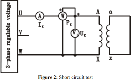
1) Connect the circuit as per Figure 2. The HV winding is connected to the power supply, while the LV winding has the short circuit. An additional ammeter can be inserted in the path of the short
circuit as optional/advanced work.
2) Select appropriate ranges for all meters, and turn the control knob of autotransformer counter clockwise (CCW) to the end, setting the output voltage to zero (0 volts).
3) Switch on the main power with the key, press the Start button, then turn the autotransformer knob to get IK = 0.2 IN on ammeter A. Measure several sets of UK, IK, PK while increasing the regulated voltage from the value for 0.2 IN to 1.1 IN, recording your results in Table 2. Be sure to measure IK = IN. Measure Ishort as optional/advanced work with each set, if of interest.
4) When finished measurements, press the Stop button, and switch off the main power with the
key. Disassemble your circuit, removing all cables. Return the cables to the drawer.
Note: Due to the high currents during the short circuit test, the equipment can suffer heating effects which biases results. It is advisable to make measurements as quickly as possible, and it is acceptable
to only switch on the power during measurements using the Start – Stop buttons.
6. Laboratory report
Your report must have the following:
6.1 Cover page
Include title, name, and student ID number.
6.2 Abstract
Write a 3 or 4 sentence summary of the experiment, any problems, and summarize the results.
6.3 Experimental results
Include Tables 1 and 2.
6.4 Discussion
Include the following:
(1) Transformation ratio calculation
Calculate the ratios from the experimental data and take the average value as the ratio:
K = UAX/Uax
(2) Plot the no load characteristics and calculate the relevant parameters
|
Including the equivalent circuit accordingly |
1) Plot the no-load characteristics:
U0 =f(I0)
P0 =f(U0)
cos φ0 =f(U0), where cosϕ0 = ![]()
2) Excitation parameters
Look up values of I0 and P0 at U0 = UN in the no load characteristic curve, then calculate the excitation parameters according to:
![]() 0
0
![]() I0(2) ,
I0(2) ,
![]() Z = U0 and
Z = U0 and
![]() I
I
X = m
![]()
![]()
![]()
![]() (3) Plot the short-circuit characteristics and calculate the short-circuit parameters
(3) Plot the short-circuit characteristics and calculate the short-circuit parameters
|
Including the equivalent circuit accordingly |
1) Plot the short-circuit characteristics:
UK =f (IK)
PK =f (IK)
cos φK =f (IK)
2) Parameters calculation
Look up values of UK and PK at IK = IN in the short circuit characteristics curve, and then
calculate the short-circuit parameters at θ (℃):
Equiv(r)![]() len(=)
len(=)![]() am
am![]()
![]()
![]()
![]() asi(n)d(d)e: XK(') =
asi(n)d(d)e: XK(') = ![]()
![]()
rK = ![]() , ZK =
, ZK = ![]() , and XK =
, and XK = ![]()
Short-circuit loss PKN equals to IN(2)rK ,750C when IK = IN .
where
rK ,750C = rK ,θ
234.5 + 75
234.5 +θ
, 234.5 is the coefficient of copper conductor.
Comment on your graphs and results!!!
6.5 Conclusion
Briefly describe the experiment as you undertook it, the major findings, any errors or difficulties
that you found, and comment on the relevance to your study.
6.6 Prelab
Give answers to the Prelab questions.
6.7 References
List any textbooks or other reference material you referred to in your write-up.
7. Assessment
Your individual formal report for this experiment should be submitted before the deadline. This report is worth 15% of module CAN102.
2023-07-26
Single-phase Transformers