2022/23 Electromagnetics, Antennas and Propagation Assignment No. 1
Hello, dear friend, you can consult us at any time if you have any questions, add WeChat: daixieit
2022/23 Electromagnetics, Antennas and Propagation Assignment No. 1
Introduction
Most real-life electromagnetic problems do not fall into a class that can be solved by
analytical methods. For these common situations, we must resort to numerical approximate solutions [1].
Numerical methods are becoming ubiquitous in engineering practice as digital computer
speed and memory capacity continue to increase. Among the powerful methods are those using finite differences (FD), finite elements, or methods of moments [2],[3]. The students are referred to the Lectures on “Numerical Methods” and references therein for further
details about different methods and commercial software.
Assignment
Task 1 (80%)
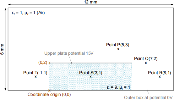
Write a computer program to implement the finite difference method that will solve the
scenario shown in the figure below. Notice that the potential difference between the
enclosing box and the central metal plate is 15V and the background is air unless otherwise stated. The program can be in any computer language that is available within the School.
Learn how to use the Partial Differential Equation Toolbox of Matlab, FREEFEM
(https://freefem.org/) or CST Microwave Studio® (E-Static Solver) available in the School of Engineering’s PCs.
Using your programme:
1. Calculate the potential at points P, Q, R, S and T when the background is air (as shown in the sketch) or a dielectric εr = 2.
2. Draw a contour map showing the potential.
3. Calculate the magnitude of the electric field |E| and the flux density |D| at P, Q, R, S and T.
4. Calculate the capacitance per unit length (i) between the central metal plate and the bottom boundary and (ii) between the central metal plate and the top boundary using your finite difference data and compare them with those of parallel plate capacitors of the same size neglecting fringing fields (i.e., fields outside the capacitor are neglected).
5. Using the capacitances per unit length from 4, calculate the total capacitance per unit length of the stripline neglecting fringing fields.
6. If the structure were a transmission line extending into the page, what is the velocity of the electromagnetic wave along the line? Do this using your finite difference data as
well as using the simple parallel plate assumption.
Using the Partial Differential Equation Toolbox of Matlab, FREEFEM or CST MWS:
7. Repeat (1) and (2) and compare the results. State any approximation that you may have used.
Task 2 (20%)
Survey the developments of coplanar waveguides for millimetre-waves (f = 30 to 300 GHz)
in the technical literature. Create a graph with at least 5 points showing measured
attenuation against frequency. Indicate clearly the source of the data points (e.g. cite technical paper).
Submission details
A report is required with a description of how you tackled the problem and the answers to the seven questions.
The report should be self-contained with a good description of the methods you used.
Your computer code (with comments) should be included as an appendix. Do not include any code for Matlab Partial Differential Equation Toolbox, FREEFEM or CST MWS.
The report should be no more than 6 sides of A4 excluding the reference list and the
appendix with your code. Use 11 point Sans Serif font (e.g. Arial), single line spacing and 1.5 cm margins all round.
In addition, you will need to add to a cover and feedback sheet to ensure you receive
targeted feedback that will support your learning. It is a requirement for students to include the completed template as the first page of every assignment that is submitted for marking.
Plagiarism, which includes, but is not limited to, a failure to acknowledge sources and using someone else code will be penalised and reported to the School Plagiarism Officer.
The report should be submitted in Acrobat PDF format via Canvas by the deadline set on the EMAP module’s Canvas page.
Marking criteria (task 1)
1. Introduction – a general description of the problem 5%
2. Methodology 30%
3. Results and discussion 40%
4. Use of references with full reference list provided 5%
5. Report and structure 10%
6. Good command of Partial Differential Equation Toolbox of Matlab 5%
7. Good programming practice – annotated source code 5%
Benchmark statements of expectations
An excellent report will present succinctly the theory behind the finite difference method with
pertinent citations to the literature, will explain the methodology followed to solve the
questions and will provide a suitable discussion when comparing the results obtained with the student’s programme, the Matlab toolbox/FREEFEM/CST MWS and the analytical
solutions (under pertinent assumptions), including your consideration of accuracy.
A failing report will be one that is not structured, misses questions, fails to provide the
computer code as an appendix, and lacks of discussion and details on how the assignment has been tackled.
[1] M. N.O. Sadiku, Computational Electromagnetics with MATLAB, CRC Press, 2018.
[2] X.-Q Sheng and W. Song, Essentials of Computational Electromagnetics, Wiley- Blackwell, 2012.
[3] D. B. Davidson, Computational Electromagnetics for RF and Microwave Engineering, Cambridge University Press, 2010.
2023-07-22