ES96Z0 ELECTRICAL MACHINES AND DRIVES Summer 2019
Hello, dear friend, you can consult us at any time if you have any questions, add WeChat: daixieit
ES96Z0
MSc Examinations: Summer 2019
ELECTRICAL MACHINES AND DRIVES
1.
(a) Explain how a synchronous machine, acting as a generator can deliver varying amounts of reactive power to the grid whilst maintaining constant real power output? (3 marks)
(b) A star-connected 2-pole synchronous generator, rated at 600 MVA, delivers 400 MW to a 50 Hz infinite bus with a line voltage of 22 kV at a power factor of 0.85 lagging. The synchronous reactance is 0.8 Ω per phase and the stator resistance can be neglected.
Calculate:
(i) The prime mover torque (2 marks)
(ii) The generator excitation voltage (7 marks)
(iii) The load angle (3 marks)
(c)
(i) What is the maximum real power output at a power factor of 0.85 lagging? (2 marks)
(ii) Why in many machines can the rated VA not be achieved at low lagging power factors? (2 marks)
(d) The manufacturer is proposing to use the machine in a 60 Hz system. Which of the following variables or parameters will change and why?
(i) Shaft speed (1 mark)
(ii) Synchronous reactance (2 marks)
(iii) Rated VA (3 marks)
(Total 25 Marks)
2.
(a) Explain the principal behind speed control, by varying the armature voltage, in a separately excited DC machine. (2 marks)
(b) A separately excited DC machine has an open circuit emf of 460 V at the rated speed of 1750 rpm and at rated field current. If the armature resistance is 0.8 Ω, calculate the armature supply voltage to deliver a load torque of 120 Nm at 1500 rpm. Neglect brush drop. By how much should the supply voltage be reduced to maintain constant speed if the load torque falls to 30 Nm? (10 marks)
(c) The DC machine of part (b) was replaced during an upgrade by a 4-pole 22 kW star connected induction machine. The machine has the following parameters:
- Stator resistance = 0.4 Ω
- Stator leakage reactance = 0.7 Ω
- Rotor leakage reactance = 0.7 Ω
- Rotor resistance (referred) = 0.3 Ω
Difficulties were experienced in starting against the load which requires a starting torque of 120 Nm. The supply voltage is 400 V. Calculate the starting torque, neglecting the magnetizing branch and comment on the result. (10 marks)
(d) How can the rotor of a cage rotor induction machine be designed to improve starting torque but limit starting current?
(3 marks)
(Total 25 Marks)
3. A separately excited direct current motor has the rated power of 7 kW and the rated velocity of 2850 rpm. The ratio of the rated EMF and angular velocity is equal to 0.75 V/(rad/s). The ratio of the rated torque and armature current is 1.3 N m/A. Assume that the armature resistance is 0.34 Ω .
(a) Compute the following parameters of the motor:
(i) Rated angular velocity in rad/s. (1 mark)
(ii) Rated torque. (1 mark)
(iii) Rated armature current. (1 mark)
(iv) Rated EMF. (1 mark)
(v) Rated voltage. (1 mark)
(b) The armature winding of the motor is connected to a DC voltage source. An additional resistor of 10 Ω is placed in series to the armature winding. The load torque applied to the motor shaft is active and equals to 10 N m. The magnetisation flux is rated and constant. The motor does not rotate.
(i) Determine the value of the DC voltage applied to the armature winding. (2 marks)
(ii) Compute the value of the velocity in rad/s after the magnetisation flux was reduced by 25%. (2 marks)
(iii) For case (ii), determine if the DC machine works as a motor or a generator. (1 mark)
(c) For the motor’s angular velocity regulation, a two loop cascade control system is implemented according to Figure 3.1. The system utilizes a P-controller of the velocity and an I-controller of the armature current. The excitation voltage is rated and constant. The block diagram of the regulation system is depicted in Figure 3.2. Its parameters are explained in Table 3.1.
(i) Define the variables labelled 1, 2 and 3 in Figure 3.2. (1 mark)
(ii) The parameters values are: c1Φr = 0.75 V/(rad/s), c2Φr = 1.3 N m/A, RaΣ = 1.1 Ω, ki =0.4 V/A, kω = 0.028 V/(rad/s). The angular velocity reference voltage is 5 V, the proportional gain of the velocity controller is 5, and the ammeter in Figure 3.1 shows 8 A. The system operates in a steady state. Compute the angular velocity of the motor and the value measured by the voltmeter. (3 marks)
(iii) For case (c)(ii), the load torque and the velocity reference voltage do not change. The excitation voltage (magnetic flux) is reduced by 25%. Determine the new steady state angular velocity of the motor. (3 marks)
(iv) For case (c)(ii), assume that the angular velocity feedback is disconnected (uω = 0 V), the load torque is active and the gain of the velocity controller becomes 0.5. Explain what will happen to the motor’s angular velocity. (3 marks)
(d) For the control system in Figure 3.2, design the controller of the armature current to provide module optimum tuning of the current closed loop, assuming Tµ = 0.
(i) Determine the transfer function and type of the controller required. (4 marks)
(ii) Calculate parameters of the transfer function of the controller for RaΣ = 1.1 Ω, ki = 0.4 V/A, kPC = 22 V/V and TaΣ = 0.05 s.
(1 mark)
(Total 25 Marks)

4. A three-phase squirrel cage induction machine has the following rated parameters: the shaft power is 7 kW, the phase voltage is 230 V, the power factor is 0.85, the efficiency is 80%, the frequency is 50 Hz and the synchronous velocity is 1500 rpm. Assume that the rated velocity is 1460 rpm. The stator winding is star connected.
(a) Compute the following parameters of the motor:
(i) Rated angular velocity in rad/s. (1 mark)
(ii) Rated slip. (1 mark)
(iii) Rated torque. (1 mark)
(iv) Rated stator current. (1 mark)
(v) Number of pole pairs. (1 mark)
(b) Assume the rated critical torque is 100 N m and the rated critical slip is 10%. A rated three-phase voltage is applied to the stator winding and the motor velocity is 1480 rpm. Compute the following values using simplified Kloss formula:
(i) The slip of the motor and the motor load torque. (4 marks)
(ii) The velocity in rad/s of the motor when the frequency is reduced to 45 Hz and
V/f=const control is implemented. The load torque remains the same. The equations for critical slip, critical torque and no load velocity are given below
 (6 marks)
(c) The block diagram of the vector control system of the motor’s angular velocity is shown in Figure 4.1. The d-q frame is aligned with the rotor flux linkage vector in the d axis. There are four controllers in the system: Angular Velocity P-Controller (AVC), rotor Flux Linkage I-Controller (FLC), two Current PI-Controllers (CC1 and CC2). The Flux Sensor (FS) and the Vector Computation block (VC) are used to determine the position and magnitude of the rotor flux linkage vector. At specific moment in time, the system is in a steady state and the components of the rotor flux linkage vector in a and b axes are 0.8 Wb and 0.2 Wb, respectively. The reference of the angular velocity is 100 rad/s, the gain of the AVC controller is 5, the instantaneous stator current values in U, V and Wphases are 4.34 A, 5.63 A and -9.97 A, respectively. For this moment in time:
(i) Determine the angular position of the d-q reference frame with respect to the a axis. (2 marks)
(ii) The output signal values of the FLC and AVC. (3 marks)
(iii) Calculate the angular velocity of the motor. (1 mark)
(iv) The dynamics of the rotor flux linkage and the torque are described by the following equations
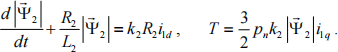
Assume that the i1d and i1q feedbacks were disconnected. The load torque was decreased by 20%, the reference velocity and the reference rotor flux linkage did not change. Compute the steady state angular velocity value and the d and q axes stator currents. (4 marks)
(Total 25 Marks)

2023-07-19