ES96Z0 ELECTRICAL MACHINES AND DRIVES 2018
Hello, dear friend, you can consult us at any time if you have any questions, add WeChat: daixieit
ES96Z0
MSc Examinations : June 2018
ELECTRICAL MACHINES AND DRIVES
1.
a) Briefly explain the excitation system in brushless synchronous generators and contrast them with brushed machines. (2.5 Marks)
b) Consider a synchronous generator acting alone. Briefly describe with the aid of phasor diagrams, the impact of increased loading on the terminal voltage for (i) Lagging loads and (ii) Leading loads. Describe the impact of the load increase on the power factor, the internal EMF and the torque angle. (2.5 Marks)
c) You have just tested a 3 phase, 4-pole, 50 Hz, delta-connected synchronous machine at its rated field current of 15 A. You measured an open circuit line-to-line terminal voltage of 650 V anda short circuit line current of 950 A at the rated field current under synchronous speed. You also measured a DC current of 80 A after applying a DC voltage of 10 V between 2 of the 3 stator phases. Assume that the open circuit characteristic relating the rotor current to the no-load terminal voltage is linear.
(i) Calculate the machines synchronous speed, the per-phase armature resistance, the internal EMF and the synchronous reactance. Sketch the per-phase equivalent circuit of this synchronous machine.
(ii) Assume the machine has a synchronous reactance of 1.17 Ω, negligible armature resistance and is to operate as a synchronous motor at 0.8 Power Factor leading from a 3 phase AC supply with a line-to-line voltage of 400 VRMS. Calculate the internal EMF, output torque and load angle required for the machine to drive a 70 hp load if it is 95% efficient. Sketch the phasor diagram of the machine under steady-state conditions (1 hp = 746 Watts). (10 Marks)
d) The synchronous machine in (c) is now to act as a generator with a 400 VRMS line-to line terminal voltage supplying 95 kW of electrical power.
(i) Determine the rotor current and torque angle required for this machine to deliver electrical power at 0.8 PF lagging recalling that the open circuit terminal voltage is 650 Vat the rated rotor current of 15 A and that the open circuit characteristic is linear.
(ii) If the rotor current is doubled with the electrical load remaining unchanged, sketch the impact of this on the phasor diagram of the synchronous generator and calculate the new terminal current and power factor. (10 Marks)
(Total: 25 Marks)
2. a)
(i) Briefly explain “Armature Voltage” and “Field Current” control in a separately excited DC motor. Explain what is meant by “Field Weakening” .
(ii) Explain the difference between separately excited and self-excited DC machines. (iii) Explain the difference between a series and shunt DC motor. (5 Marks)
b) You have just performed no-load and locked rotor tests on a 3-phase, 600 V, 50 Hz,
star-connected induction motor and obtained the set of results shown in Table Q2.

You have also done DC measurements by supplying 20 V between 2 stator phases of the induction motor and recording a DC current 500 A. Based on these measurements, derive the per-phase IEEE recommended equivalent circuit of the induction motor. (10 Marks)
c) A 400 V, 3-phase, star-connected, 50 Hz, 8-pole induction motor has a rotational speed of 700 rpm under full load conditions. The IEEE recommended equivalent circuit has the following per-phase parameters.
R1=0.2 Ω, R2’=0.15 Ω, X1=0.25 Ω, X2’=0.33 Ω and Xm=40 Ω
The frictional and windage (rotational) losses of the machine are 5 kW and the core
losses can be considered to be negligible. Calculate:
(i) The input power and power factor under full-load conditions with 400 V line- to-line voltage at the input.
(ii) The air-gap power and converted power under full load conditions.
(iii) The induced torque under full load conditions.
(iv) The output power and efficiency under full load conditions.(10 Marks)
(Total: 25 Marks)
3. The nameplate of a separately excited direct current motor contains the following data: the rated power is 3 kW, the rated angular velocity is 2800 rpm, and the rated voltage is 220 V. The ratio of the rated EMF and angular velocity is equal to 0.73 V/(rad/s). The ratio of the rated torque and armature current is 1.5 N m/A.
a) Compute the following parameters of the motor:
(i) Rated angular velocity in rad/s.
(ii) Rated torque.
(iii) Rated armature current.
(iv) Rated EMF.
(v) Armature resistance. (5 Marks)
b) The armature winding of the motor is fed from a DC voltage supply of 200 V. The resistance of the armature winding is 0.9 Ω. An additional resistor is connected in series to the armature winding. The load torque applied to the motor shaft is active and equal to 8 N m. The magnetisation flux is rated and constant. The motor does not rotate.
(i) Calculate the value of the additional resistance. (2 Marks)
(ii) The armature winding is disconnected from the DC supply and short-circuited via
the additional resistor. Determine the value of the motor’s angular velocity. (2 Marks)
(iii) For case (ii), does the DC machine operate as a motor or a generator? (1 Mark)
c) A two loop cascade control system is used for the motor’s angular velocity regulation as shown in Figure Q3(a). The velocity and armature current controllers are both PI- controllers. The excitation flux is rated and constant. The block diagram of the control system is shown in Figure Q3(b). Its parameters are defined in Table Q3(a).
(i) Define the variables labelled 1, 2 and 3 in Figure Q3(b)? (1 Mark)
(ii) The control system operates in a steady state. The ammeter and voltmeter in
Figure Q3(a) measure 8 A and 205 V, respectively. c1Φr = 0.73 V/(rad/s), c2Φr = 1.5 N m/A, RaΣ = 2 Ω, ki =0.4 V/A, kPC = 22. Compute the steady state load torque, angular velocity and the armature current reference voltage. (3 Marks)
(iii) The integral part of the PI-controller of the armature current is disconnected. The
gain of the proportional part of the armature current controller is equal to 4. The parameters of the system are the same as in c.(ii). The load torque and the angular velocity reference do not change. Determine the values shown by the ammeter and voltmeter. Compute the armature current reference voltage. (3 Marks)
(iv) Assume that the armature current feedback is disconnected by mistake (ui=0 V).
How will this influence the ammeter and voltmeter measurements and the value of the steady state armature current reference voltage for the conditions of cases c.(ii) and c.(iii)? (3 Marks)
d) For the control system in Figure Q3(b), design the controller of the armature current to provide module optimum tuning of the armature current closed loop, assuming Tµ = 0 s.
(i) Determine the type of the controller required. (2 Marks)
(ii) Calculate parameters of the transfer function of the controller for RaΣ = 2 Ω,
ki = 0.4 V/A, kPC = 22 V/V and TaΣ = 0.05 s. (1 Mark)
(iii) Sketch the schematic of the controller based on an operational amplifier. (2 Marks)
(Total: 25 Marks)

4. The nameplate of a three-phase squirrel cage induction machine contains the following data: the rated shaft power is 3 kW, the rated line-to-line voltage is 380 V, the rated efficiency is 0.8, the rated power factor is 0.86, the synchronous velocity is 3000 rpm and the rated velocity is 2900 rpm.
a) Compute the following parameters of the motor:
(i) Rated angular velocity in rad/s.
(ii) Rated phase voltage.
(iii) Rated stator current.
(iv) Rated torque.
(v) Rated slip. (5 Marks)
b) The machine is fed from a controlled voltage source which provides V/f = const ratio, leading to a constant rated critical torque of 25 N m. In a steady state, the frequency of the supplied voltage is 40 Hz, the machine’s angular velocity is 246 rad/s and the load torque is 10 N m. The number of pole pairs is equal to one. Compute the steady state values of
(i) The no load angular velocity. (1 Mark)
(ii) The slip. (1 Mark)
(iii) The critical slip using the simplified Kloss formula. (3 Marks)
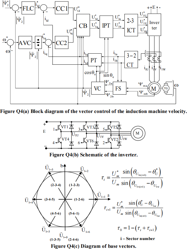
c) The vector control of the motor’s angular velocity is implemented in the d-q frame aligned with the rotor flux linkage vector in the d axis according to the block diagram in Figure Q4(a). The control system includes an Angular Velocity PI-Controller (AVC), a rotor Flux Linkage PI-Controller (FLC), two Current PI-Controllers (CC1 and CC2), a Compensation Block (CB), a Flux Sensor (FS) and a Vector Computation block (VC). At specific moment in time, the rotor flux linkage vector magnitude is 1 Wbandits angle with respect to stator axis a is 30 degrees. The instantaneous values of the stator currents in phases U, Vand Ware 2 A, 2 A and –4 A, respectively. The instantaneous values of the stator voltages in phases U, Vand Ware 100 V, 110 V and –210 V, respectively. For this moment in time compute:
(i) The d and q axes stator currents. (3 Marks)
(ii) The d and q axes stator reference voltages. (4 Marks)
d) Space Vector PWM modulation of the stator voltage vector is used in the system in Figure Q4(a). The modulation is implemented according to Figures Q4(b) and Q4(c), where E=600 V. For the moment in time and stator voltages specified in part c:
(i) Determine required nonzero base vectors and their amplitude Um. (2 Marks)
(ii) Determine the numbers of transistors used for the realisation of the required nonzero base vectors. (1 Mark)
(iii) Compute duty ratios of the required base and zero vectors. (5 Marks)
(Total: 25 Marks)
2023-07-19