5CCE2ECM Electricity and Magnetism
Hello, dear friend, you can consult us at any time if you have any questions, add WeChat: daixieit
5CCE2ECM Electricity and Magnetism
You will be required to undertake this alternative assessment in place of your deferred coursework
component or as reassessment for your failed coursework attempt. Please note, this also includes in class tests which are scheduled within term outside of the examination window.
This alternative assessment for 5CCE2ECM (2022/23 academic year) is designed to replace the outstanding
components below:
Assessment 1 – Quiz (covering Topics 1 and 2)
Assessment 2 – MATLAB/Simulink exercise on three-phase power systems
The alternative assessment consists of two parts, and you are required to complete both – you will find
the questions starting on PAGE 2.
Submission requirements:
Your submission should be maximum of 6 (six) pages and contain your worked solutions and images of any plots you generate. You should use 12pt Calibri (or alternative) sans-serif font with 1.5 line spacing. The page limit includes figures, all plots should have a title, labelled axes and units. Extra pages will not be marked.
The alternative assessment is due to be released on Thursday 29th June.
As clarified in the email sent to students in June (Engineering Assessments Period 3 - August Information, sent 5th June), no extensions will be permitted.
Coursework is due 4pm, Thursday 27th July 2023.
Those with approved KIPS/PAA in place please refer to communications received from the Department (PAA Information for Engineering Assessments Period 3 - August, sent 6th June) for further information. If you have not received this, then please contact the UG / PGT office as soon as possible.
Submissions will not be accepted after the deadline has passed, please ensure that you leave plenty of time to check over and upload your work. If you are unable to submit by this deadline, emailengineering- ug@kcl.ac.ukand apply for mitigation as soon as possible. Information on mitigation can be found viaKA- 01744 · Student Services Online (kcl.ac.uk)
Submissions will not be accepted via email; submissions must be made via the correct KEATS area. Further information on the submission area and where to submit can be found via –Course: Engineering Coursework Submissions - August 2023 (kcl.ac.uk).
Support for carrying out this assessment is available:
Please contact Dr Mark Ainslie (mark.ainslie@kcl.ac.uk) via email regarding Part 1 and Dr Grazia Todeschini (grazia.todeschini@kcl.ac.uk) regarding Part 2, before 4pm on Thursday 20 July.
Part 1, Electromagnetism
Question 1 (30 marks)
Three fixed point charges, A, B and C, are located on a two-dimensional (x, y) plane, with a central origin point at (0, 0).
Charge A: 20 mC at position (– 1 mm, – 1 mm)
Charge B: – 15 mC at position (1 mm, 0 mm)
Charge C: 30 mC at position (0 mm, 2 mm)
a) Sketch the plane showing each charge, and indicate the direction of the electric field due to each point charge, with respect to a position P (2 mm, 2mm) (6 marks)
b) Calculate the magnitude and direction of the electric field E at position P (2 mm, 2 mm) (24 marks)
Question 2 (20 marks)
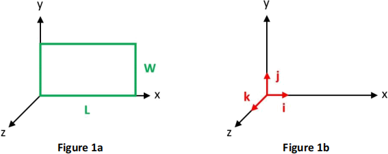
Consider the wire loop shown in Figure 1a. The length is L = 20 cm and the width is W = 25 cm. The wire is immersed in a magnetic field, and the relevant unit vectors are shown in Figure 1b.
For each one of the conditions below, calculate both magnitude and direction of the induced emf (clockwise, counterclockwise, or ‘none’). You must show your working and/or reasoning.
Note that the field may be a function of space only, of time only, or a function of both time and space.
a) B = 0.1 [T/m] yk (4 marks)
b) B = 0.5 [T/s] tk (4 marks)
c) B = –0.1 [T/m/s] ytk (4 marks)
d) B = 0.25 [T/m/s] xtj (4 marks)
e) B = 0.05 [T/m/s] yti (4 marks)
Part 2, Simulink
Question 3 (50 marks)
Consider a system consisting of a three-phase power source, an ideal three-phase two-winding transformer and a load, with the following characteristics:
Transformer
Rated power = 20 kW
Primary voltage = 13 kV, wye-ground connected
Secondary voltage = 400 V, delta connected
Power source
Rated voltage = 13 kV, Source resistance = 0.01 Ω, source inductance = 2 mH.
Load
P = 10 kW, Q = 5 kW, rated voltage = 400 V, delta connection (use a three-phase parallel load) Rated system frequency = 50 Hz
Create a Simulink including the transformer, with the power source connected at the primary side, and the load connected at the secondary side . If some data is missing (for example, in order to populate some of the masks in Simulink), you should make appropriate assumptions based on what was discussed in the lab and during the lectures, and based on engineering judgment.
You will need to add also appropriate measurement masks to be able to plot the quantities required in the questions (Hint: when you include the voltage/current measurement block on the delta- connected side of the transformer, you will need to change the voltage measurement to ‘phase-to- phase’ to avoid receiving an error when trying to run the model . This was discussed as part of the module).
It is suggested to set the run time to 0.1 s and to use a discrete simulation time step.
Once the model is set up, answer the questions below (Please note that if figures are not readable or not well formatted, a penalty will be applied up to 20% of the mark awarded to each question. Graphs lacking units and labels will result in a mark of 0 points, even if the waveform is correct)
1. A screenshot of the model, of the parameters tab for the power source, the transformer and the load. If necessary, explain any assumptions you made when building the model . (10 marks)
2. A plot of the phase-to-phase secondary voltage graph and calculation to show it matches the expected value (10 marks)
3. A plot of three-phase secondary current graph and calculations to show that they match the expected value (10 marks)
4. A plot of three-phase primary currents and calculations to show that they match the expected value (10 marks)
5. A plot of the active and reactive power measured at the high side of the transformer, and observations about any discrepancies you may observe with the rated value (10 marks)
2023-07-15