CST3562 Case Study
Hello, dear friend, you can consult us at any time if you have any questions, add WeChat: daixieit
CST3562 Case Study
Introduction
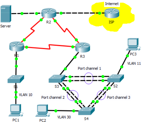
An International Travel Agency (ITA) network is shown in the topology diagram. The network has been implemented based on the requirements but some of the required functions are not working properly. Carefully examining the requirements and troubleshooting the network as necessary.
Download the Packet Tracer activity file and the word document (this document) from Unihub and rename both files by replacing the M00xxxxxx with your student number. This case study uses a variety of technologies including routing, port security, EtherChannel, DHCP, NAT and PPP. Devices in the topology have been pre-configured with some errors introduced. Therefore the configurations do not entirely meet with the requirements. Your task is to review the requirements, isolate and resolve any issues, and then document the steps you took to verify the requirements.
Topology
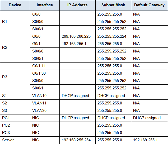
Addressing Table
Packet Tracer file will randomly generate address sets automatically. Therefore, each student may get different addresses. Filling this address table based on the information from your packet tracer instruction window. You need this information as the reference for your troubleshooting.
Requirements:
DHCP
· R1 is the DHCP server for the R1 LAN.
Switching Technologies
· Port security is configured to only allow PC1 to access S1's F0/3 interface. All violations should disable the interface.
· Link aggregation using EtherChannel PAgP protocol is configured on S2, S3, and S4. Ports should actively ask if the other side can or will participate.
Routing
· All routers are configured with OSPF process ID 1 and no routing updates should be sent across interfaces that do not have routers connected.
· R2 is configured with a default route pointing to the ISP and redistributes the default route.
· NAT is configured on R2 and no untranslated addresses are permitted to cross the Internet.
WAN Technologies
· The serial link between R1 and R2 uses HDLC encapsulation.
· The serial link between R2 and R3 uses HDLC encapsulation.
· The serial link between R1 and R3 uses PPP with PAP.
Connectivity
· Devices should be configured according to the Addressing Table.
· Every end device should be able to ping every other device.
Troubleshooting Documentation
|
Device |
Error |
Correction |
|
|
|
|
(Add more rows if needed)
Verification Documentation
Capture output from verification commands and provide documentation proving that each of the requirements has been satisfied.
Submission
Save this document (troubleshooting and verification), save the Packet Tracer activity file you have completed, submit both files via Unihub before the deadline which is by the Friday of Week 24.
Packet Tracer scores: 60%. The troubleshooting/verification documentation: 40%.
2023-07-01