CST3562 Lab Test 3
Hello, dear friend, you can consult us at any time if you have any questions, add WeChat: daixieit
CST3562 Lab Test 3
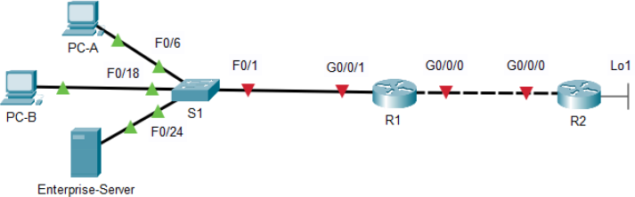
Topology
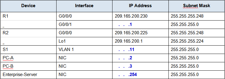
Addressing Table
The addresses will be randomly generated, therefore each student may get a different ip address set. Fill the address table below based on the information from the Packet Tracer Instruction Window
Objectives
Part 1: Build the Network and Configure Basic Device Settings
Part 2: Configure and verify NAT for IPv4
Part 3: Configure and verify PAT for IPv4
Part 4: Configure and verify Static NAT for IPv4
Scenario
Network Address Translation (NAT) is the process where a network device, such as a Cisco router, assigns a public address to host devices inside a private network. The main reason to use NAT is to reduce the number of public IP addresses that an organization uses because the number of available IPv4 public addresses is limited.
An ISP has allocated the public IP address space of 209.165.200.224/29 to a company. This network is used to address the link between the ISP router (R2) and the company gateway (R1). The first address (209.165.200.225) is assigned to the g0/0/0 interface on R2 and the last address (209.165.200.230) is assigned to the g0/0/0 interface on R1. The remaining addresses (209.165.200.226-209.165.200.229) will be used to provide internet access to the company hosts. A default route is used from R1 to R2. The internet is simulated by a loopback address on R2.
In this lab test, you will configure various types of NAT. You will test, view, and verify that the translations are taking place, and you will interpret the NAT/PAT statistics to monitor the process.
Instructions
Part 1: Configure Basic Device Settings
In Part 1, you will configure basic settings on the Routers, Switch, and PC hosts.
Step 1: Configure basic settings for each router.
a. Disable DNS lookup to prevent the router from attempting to translate incorrectly entered commands as though they were host names.
b. Assign class as the privileged EXEC encrypted password.
c. Assign cisco as the console password and enable login.
d. Assign cisco as the VTY password and enable login.
e. Encrypt the plaintext passwords.
f. Create a banner Authorized Users Only that warns anyone accessing the device that unauthorized access is prohibited.
g. Configure IP addresses for the interfaces on R1 and R2 as specified in the addressing table above.
h. Configure a default route to the ip address of R2 g0/0/0 from R1.
i. Save the running configuration to the startup configuration file.
Step 2: Configure basic settings for the switch.
a. Disable DNS lookup to prevent the router from attempting to translate incorrectly entered commands as though they were host names.
b. Assign class as the privileged EXEC encrypted password.
c. Assign cisco as the console password and enable login.
d. Assign cisco as the VTY password and enable login.
e. Encrypt the plaintext passwords.
f. Create a banner Authorized Users Only that warns anyone accessing the device that unauthorized access is prohibited.
g. Shutdown all interfaces that will not be used.
h. Configure vlan 1 interface IP address and default gateway for the switch.
i. Save the running configuration to the startup configuration file.
Step 3: Configure IP address, subnet mask, and default gateway for PC-A, PC-B and Enterprise-Server.
Part 2: Configure and verify NAT for IPv4
In Part 2, you will configure and verify NAT for IPv4.
Step 1: Configure NAT on R1 using a pool of three addresses, 209.165.200.226-209.165.200.228.
a. Configure a simple access list 1 that defines what hosts are going to be allowed for translation. In this case, all devices on the R1 LAN are eligible for translation.
b. Create the NAT pool, and give it a name PUBLIC_ACCESS and a range of addresses to use.
Note: The netmask parameter is not an IP address delimiter. It should be the correct subnet mask for the addresses being assigned, even if you are not using all the subnet addresses in the pool.
c. Configure the translation, associating the ACL and Pool to the translation process.
Note: Three very important points. First, the word ‘inside’ is critical to the operation of this kind of NAT. If you omit it, NAT will not work. Second, the list number is the ACL number configured in a previous step. Third, the pool name is case-sensitive.
d. Define the inside interface.
e. Define the outside interface.
Step 2: Test and Verify the configuration.
Generate traffic from multiple devices: From PC-A, PC-B, and Enterprise-Server, use the -t parameter with the ping command to send a non-stop ping to R2’s Lo1 interface (ping -t 209.165.200.1). If the ping was unsuccessful, troubleshoot and correct the issues. After a few seconds, stop all the pings on PC-A, PC-B and Enterprise-Server using the CTRL-C key combination.
a. On R1, display the NAT table on R1 with the command show ip nat translations.
Document the output of the show ip nat translations command on R1:
b. From S1, ping the Lo1 interface (209.165.200.1) on R2. Was the ping successful? If not, why not?
c. Clear the NAT translations and we will move on to PAT.
R1# clear ip nat translation *
Part 3: Configure and verify PAT for IPv4
In Part 3, you will replace NAT with PAT to a pool of addresses, and then with PAT using an interface.
Step 1: Remove the translation command on R1.
The components of an Address Translation configuration are basically the same; something (an access-list) to identify addresses eligible to be translated, an optionally configured pool of addresses to translate them to, and the commands necessary to identify the inside and outside interfaces. From Part 2, our access-list (access-list 1) is still correct for the network scenario, so there is no need to recreate it. We are going to use the same pool of addresses, so there is no need to recreate that configuration either. Also, the inside and outside interfaces are not changing. To get started in Part 3, remove the command that ties the ACL and pool together.
R1(config)# no ip nat inside source list 1 pool PUBLIC_ACCESS
Step 2: Add the PAT command on R1.
Now, configure for PAT translation to a pool of addresses (remember, the ACL and Pool are already configured).
Step 3: Test and Verify the configuration.
a. Let’s verify PAT is working. From PC-B, ping the Lo1 interface (209.165.200.1) on R2. If the ping was unsuccessful, troubleshoot and correct the issues. On R1, display the NAT table on R1 with the command show ip nat translations.
Document the output of the show ip nat translations command on R1:
b. From PC-A, ping the Lo1 interface (209.165.200.1) on R2. If the ping was unsuccessful, troubleshoot and correct the issues. On R1, display the NAT table on R1 with the command show ip nat translations.
Document the output of the show ip nat translations command on R1:
c. PAT to a pool is a very effective solution for small-to-midsize organizations. However, there are unused IPv4 addresses involved in this scenario. We will move to PAT with interface overload to eliminate this waste of IPv4 addresses. clear translations and translation statistics:
R1# clear ip nat translation *
Step 4: On R1, remove the nat pool translation commands.
Once again, our access-list (access-list 1) is still correct for the network scenario, so there is no need to recreate it. Also, the inside and outside interfaces are not changing. To get started with PAT to an interface, clean up the configuration by removing the command that ties the ACL and pool together.
R1(config)# no ip nat inside source list 1 pool PUBLIC_ACCESS overload
Step 5: Add the PAT overload command by specifying the outside interface.
Add the PAT command that will cause overload to the outside interface.
Step 6: Test and Verify the configuration.
a. From PC-A ping the Lo1 interface (209.165.200.1) on R2. Then, on R1, display the NAT table on R1 with the command show ip nat translations.
Document the output of the show ip nat translations commend on R1:
b. From PC-B ping the Lo1 interface (209.165.200.1) on R2. Then, on R1, display the NAT table on R1 with the command show ip nat translations.
Document the output of the show ip nat translations command on R1:
Part 4: Configure and verify Static NAT for IPv4
In Part 4, you will configure static NAT so that Enterprise-Server is directly reachable from the internet. Enterprise-Server will be reachable from R2 via the address 209.165.200.229.
Step 1: On R1, configure the NAT command required to statically map an inside address to an outside address.
Configure a static mapping between Enterprise-Server’s IP address and 209.165.200.229.
Step 2: Test and Verify the configuration.
a. From Enterprise-Server, ping the Lo1 interface (209.165.200.1) on R2. On R1, display the NAT table on R1 with the command show ip nat translations.
Document the output of the show ip nat translations command on R1:
b. From R2, ping the Enterprise-Server (209.165.200.229). Verify this by pinging from R2 to 209.165.200.229. On R1, display the NAT table on R1 with the command show ip nat translations.
Document the output of the show ip nat translations command on R1:
Marking Scheme
Configurations on Packet Tracer: 60%. Verifications on this document: 40%
2023-07-01