CST3562 Lab Test 1
Hello, dear friend, you can consult us at any time if you have any questions, add WeChat: daixieit
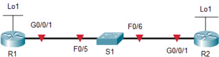
Topology
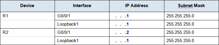
Addressing Table
The addresses will be randomly generated, therefore each student may get a different ip address set. Fill the address table below based on the information from the Packet Tracer Instruction Window
Objectives
Part 1: Configure Basic Device Settings
Part 2: Configure and Verify Single-Area OSPFv2 for basic operation
Part 3: Optimize and Verify the Single-Area OSPFv2 configuration
Scenario
You have been tasked with configuring a small company’s network using OSPFv2. R1 will be hosting an internet connection (simulated by interface Loopback 1) and sharing the default route information to R2. After the initial configuration, the organization has asked for the configuration to be optimized to reduce protocol traffic and ensure that R1 remains in control of routing.
Instructions
Part 1: Configure Basic Device Settings.
Step 1: Configure basic settings for R1, R2, and S1.
a. Disable DNS lookup to prevent the router from attempting to translate incorrectly entered commands as though they were host names.
b. Assign class as the privileged EXEC encrypted password.
c. Assign cisco as the console password and enable login.
d. Assign cisco as the VTY password and enable login.
e. Encrypt the plaintext passwords.
f. Create a banner Authorized Users Only that warns anyone accessing the device that unauthorized access is prohibited.
g. Save the running configuration to the startup configuration file.
Part 2: Configure and Verify Single-Area OSPFv2 for basic operation.
Step 1: Configure interface addresses and basic OSPFv2 on each router.
a. Configure interface addresses on each router as shown in the Addressing Table above.
b. Enter OSPF router configuration mode using process ID 56.
c. Configure a static router ID for each router (1.1.1.1 for R1, 2.2.2.2 for R2).
d. Configure a network statement with wildcard mask to advertise the network between R1 and R2 into OSPF area 0.
e. On R2 only, Configure a network statement with wildcard mask to advertise the Loopback 1 network into OSPF area 0.
f. Verify OSPFv2 is operational between the routers. Issue the command to verify R1 and R2 have formed an adjacency.
Document the output of the show ip ospf neighbor on R1:
Document the output of the show ip ospf neighbor on R2:
Which router is identified as the DR? Which is the BDR? What was the selection criteria?
g. On R1, issue the show ip route ospf command to verify that the R2 Loopback1 network is present in the routing table. Notice the default behavior of OSPF is to advertise a loopback interface as a host route using a 32 bit mask.
Document the output of the show ip route ospf on R1:
h. Ping the R2 Loopback 1 interface address from R1. Document the output of the ping test:
Part 3: Optimize the Single-Area OSPFv2 configuration
Step 1: Implement various optimizations on each router.
a. On R1, configure the interface G0/0/1 OSPF priority to 50 to ensure R1 is the Designated Router.
b. Configure the OSPF timers on the G0/0/1 of each router for a hello timer of 30 seconds.
c. On R1, configure a default static route that uses interface Loopback 1 as the exit interface. Then, propagate the default route into OSPF. Note the console message after setting the default route.
d. On R2 only, add the configuration necessary for OSPF to treat R2 Loopback 1 like a point-to-point network. This results in OSPF advertising Loopback 1 using the interface subnet mask.
e. On R2 only, add the configuration necessary to prevent OSPF advertisements from being sent to the Loopback 1 network.
f. Change the reference bandwidth on each router to 1Gbs. After this configuration, restart OSPF using the clear ip ospf process command. Note the console message after setting the new reference bandwidth.
Step 2: Verify OSPFv2 optimizations are in place.
a. Issue the show ip ospf interface g0/0/1 command on R1 and verify that the interface priority has been set to 50 and that the time intervals are Hello 30, Dead 120, and the default Network Type is Broadcast
Document the output of the show ip ospf interface g0/0/1 on R1:
b. On R1, issue the show ip route ospf command to verify that the R2 Loopback1 network is present in the routing table. Note the difference in the metric between this output and the previous output. Also note the mask is now 24 bits as opposed to the 32 bits previously advertised.
Document the output of the show ip route ospf on R1:
c. On R2, issue the show ip route ospf command. The only OSPF route information should be the default route R1 is propagating.
Document the output of the show ip route ospf on R2:
d. Ping the R1 Loopback 1 interface address from R2.
Document the output of the ping test from R2:
Marking Scheme
Configurations on Packet Tracer: 60%. Verifications/Testing/Questions on this document: 40%.
2023-07-01