ELEC2147 Past Examination Questions Practice
Hello, dear friend, you can consult us at any time if you have any questions, add WeChat: daixieit
ELEC2147 Past Examination Questions Practice
Q.1
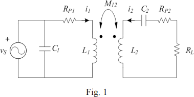
Fig. 1 shows the circuit diagram of a wireless power transfer system. The self-inductances of two coils are L1 = L2 = 101.32 µH; the mutual inductance is M12 = 10 µH; the parasitic resistances are RP1 = RP2 = 1 Ω; the capacitance of C2 is 1 nF; vS is a sinusoid with frequency of 500 kHz; the load resistance RL = 10 Ω .
(1) Find the impedances of L2 and C2 . What’s the total impedance of L2 and C2?
(2) If the peak value of vS is 100 V and the phase angle is 0, find the time domain i1(t) in the primary coil.
(3) Find the value of C1 to achieve a power factor of 100 percent.
Solution
1) ZL2 =jωL2 =j318.31 Ω, ZC2 = 1/jωC2 = -j318.31 Ω, ZL2 + ZC2 = 0
2)
(RP1 +jωL1) I1 + jωM I2 = VS,
jωM I1 + (jωL2 + 1 /jωC2 + RP2 +RL) I2 = 0
I1 = 100 (RP2 + RL) / ω2M2 + (RP1 +jωL1) (RP2 +RL)
I1 = 8.282 × 10⁻² -j2.906 × 10-1 A or 0.302 ∠- 74.09o A
I1 (t) = 0.302 cos (2π 500×103 t - 74.09o) A
3) VS / ZC1 = - Im (I1), 100 / ( 1/jωC1) = -j2.906 × 10-1, C1 = 925 pF
Q.2
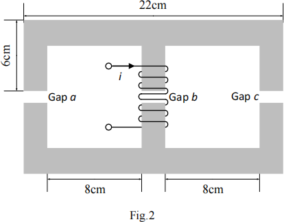
Fig. 2 shows an inductor using two identical E-shape iron core. The cross section of the core
is 2 cm × 2 cm. The air gap length is 0.1 cm. The relative permeability of the iron core is
1000. The coil has 100 turns and carries a current of i = 5 A. Assuming the fringing flux increases 5% of the air gap cross-section area.
(1) Calculate the total reluctance.
(2) Find the flux density in the air gap b.
(3) Find the inductance of this inductor.
Solution
1)
RL = RR = 2 × (0.1 + 0.05) / (1000 × 4π×10- 7 × 0.02× 0.02) = 5.968×10⁵ A turns/Wb RM = RR = 2 × ( 0.05) / (1000 × 4π×10- 7 × 0.02× 0.02) = 1.989×10⁵ A turns/Wb Ra = Rb = Rc = (0.001) / ( 4π×10- 7 × 0.021 × 0.021) = 1.804×10⁶ A turns/Wb RTotal =(RL + Ra )// (RR + Rc )+ RM + Rb = 0.5×( RL + Ra ) + RM + Rb
= 0.5×(5.968×105 +1.804×10⁶)+ 1.989×10⁵ +1.804×106
= 32.033×10⁵ A turns/Wb
2) Bb = ϕ /Ab = 100×5 / RT / (0.021 × 0.021) = 0.354 T
3) L = N2 / RT = 1002 / 32.033×105 = 3.122 mH
4) Increase number of turns or decrease air gap length
Q.3
The parameters of a 60 Hz, 24 kVA, 240:2400V step-up transformer are:
R1 = 0.03 Ω R2 = 3 Ω Rc = 1000 Ω
Xl = 0.07 Ω X2 = 6.5 Ω Xm = 150 Ω
(1) Find the rated output current (RMS value).
(2) Estimate the real power in the open-circuit test with the high-voltage winding open when the applied voltage is 240Vrms.
(3) Estimate the real power in the short-circuit test with the high-voltage winding shorted when the current in the high-voltage winding reaches the rated value.
(4) Estimate the efficiency of the transformer with 24 kW output power and a power factor of 100%.
Solution
1) IOUT = S / VOUT = 24×103 / 2400 = 10 A
2) POC = 2402 / 1000 = 57.6 W
3) I1 = 10 × IOUT = 100 A, PSC = I12 × 0.06 = 600 W
4) n = PL / (PL + POC + PSC) = 97.33 %
Q.4
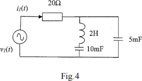
Fig.4 shows the diagram of a time-domain electric circuit. It is given that v1 (t) = 80 cos (10t) where t is the time variable.
(1) Determine the angular frequency (ω) and state the impedances of the inductor and the two capacitors in the circuit.
(2) Express Vi in phasor form
(3) Determine the input current I1 in the frequency-domain, and then express the input current i1(t) in the time domain.
(4) What is the input power factor?
(5) Calculate the apparent power (S), active power (P) and reactive power (Q) of this circuit.
Solution
1) ω=10, ZL =j ω L =j20 Ω ,
ZC_10 =1 / j ω C10 =-j10 Ω,
ZC_5 =-j20 Ω,
2) 80 ∠0o
3) ZEq =20 Ω + (ZL + ZC_10 )// ZC_5 = 20 Ω + (ZL + ZC_10 )// ZC_5 =j20 Ω I1 = 80 / (20 + j20) =80 / 28.28∠45o = 2.83∠-45o A
4) PF = cos(45o) = 0.707
5) S = V × I = (80 × 2.83) / 2 = 113.2 VA, P = S × cos(45o) = 80.03 W, Q = S × sin(45o) = 80.03 Var.
Q.5
A step-down (closely-coupled) single-phase transformer is designed for 220V/110 V and 50 Hz operation. Its full output current is rated at l0A. The transformer has been tested with the following results:
Open circuit test: Primary voltage= 220 V(rms), Primary current= 0.8 A(rms) ;
Input power= 25W.
Short circuit test: Primary voltage= 4.5 V(rms), Primary current= 10 A(rms) ;
Input power= l0W.
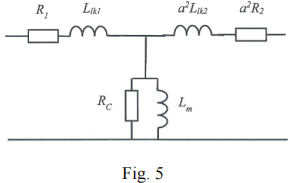
It can be assumed that the impedance of the primary winding and the reflected impedance of the secondary winding (i.e. secondary parameters reflected to the primary side) are identical. The numbers of turns of the primary and secondary windings are N1 and N2 respectively. The equivalent circuit is shown in Fig.5.
(1) What is the turns ratio a= N1/N2?
(2) State the physical meanings of the parameters (R1, R2, Re, LIkl, Ltk2 and Lm).
(3) Determine the values of these parameters of the transformer model (with the secondary parameters referred to the primary side as shown in Fig.5).
Solution
1) a = 220 / 110 = 2
2) R1, R2, = Winding resistance of the primary and seconding windings. LLK!, LLK2 = leakage inductance of the primary and secondary windings RC = core less, Lm = magnetic inductance
3) Open-circuit test: POC = 2202 / RC = 25 W, RC = 1936 Ω POC = VI cos9, 9= cos-1 (25 / 220 / 0.8) = 81.80 Xm = 220 / 0.8 / sin 81.8o = 277.84 Ω, Lm = 0.88 H
Short-circuit test: PSC =10 = 102 ×2 R1, R1 =0.05Ω, R2 = R1/a2 = 0.0125Ω
ZSC = 4.5 / 10 =0.45Ω, RSC = 2 R1 =0.1Ω,
XSC = √(ZSC2 – Req2) = 0.439Ω or 1.4 mH
Llk1 = 1.4 / 2 =0. 7 mH, a2Llk2 = Llk1 , Llk2 = 0.175 mH
Q.6

A permanent DC motor is controlled by a switched-mode power converter based on PWM duty-cycle (D) control as shown in Fig.6. It is given that the dc power supply Vdc = 200V, the armature winding resistance Ra = 1Ω, the back electromotive force E=kϕωm and electric torque Te =kϕIa, where kϕ is a machine constant, ωm is the mechanical angular frequency and ia is the armature current of the permanent DC motor. The dynamic equation of the electric torque (Te) and load torque (IL) is:
Te - TL = Fωm + J dωm /dt
where F = 0.01 Nm.s/rad is the frictional coefficient and J is the motor inertia. Now assume "steady-state" operation,
(1) Derive the equation for the "average" armature voltage of Vt.
(2) Derive the electric torque - angular speed equation.
(3) If the maximum starting torque is 80 Nm, when duty-cycle (D) = 1, determine the value of the machine constant kϕ, and the value of maximum speed of the motor at no-load.
(4) If the motor is driving a load with an equivalent load torque of TL=l0 Nm at ωm = l50 rad/s, calculate the required electric torque Te, the average armature current Ia and the duty cycle D.
Solution
1) Vt = D Vdc , D Vdc = IaRa + E
2) D Vdc = (Te / kϕ) Ra + kϕ ωm Te = (kϕ /Ra )(D Vdc - kϕ ωm)
3) Tstarting = 80 Nm @ ωm =0
80 = (kϕ / 1 )(1 x200), kϕ = 0.4
0 = (0.4 / 1 )(1 x 200 - 0.4 x ωm ), ωm = 500
4) Under steady-state condition Te - TL = Fωm,
Te - 10= 0.01 x 150, Te = kϕ xIa ,
Te =11.5 Nm
Ia =11.5 / 0.4 = 28.75 A
Te = (kϕ /Ra )(D Vdc - kϕ ωm), 11.5 = (0.4 )(D x200 - 0.4x 150), D = 0.44
Q.7
Given the instantaneous voltage and current of an electric load,
vs = Vs _ pk cos(ωt + θv)
is = Is _ pk cos(ωt + θi) ,
1) derive from first principle, showing that the instantaneous power of an electric load can be expressed as
ps = ![]() cos(θv −θi)+
cos(θv −θi)+ ![]() cos 2ωt cos(θv +θi) −
cos 2ωt cos(θv +θi) − ![]() sin 2ωt sin(θv +θi)
sin 2ωt sin(θv +θi)
2) simplify the instantaneous power equation, showing that the average power consumption of a resistive load is ![]() and an inductive load is zero.
and an inductive load is zero.
Hint: cosα cosβ= ![]() cos(α − β)+
cos(α − β)+![]() cos(α + β) cos(α + β) = cosαcosβ− αsin βsin
cos(α + β) cos(α + β) = cosαcosβ− αsin βsin
Solution
1)
ps = vs is = Vs _ pk Is _ pk cos(ωt + θv )cos(ωt + θi )
= ![]() cos(θv − θi )+
cos(θv − θi )+ ![]() cos(2ωt + θv + θi )
cos(2ωt + θv + θi )
= ![]() cos(θv − θi )+
cos(θv − θi )+ ![]() cos 2ωt cos(θv + θi ) −
cos 2ωt cos(θv + θi ) − ![]() sin 2ωt sin(θv + θi )
sin 2ωt sin(θv + θi )
2)
Resistive load, assuming θv = θi = 0 Inductive load, assuming θv = 0,θi = − π
ps = Vs _ pk Is _ pk + Vs _ pk Is _ pk cos(2ωt) 2
Ps = ![]()
![]() p
p![]() dts_pk(=)
dts_pk(=) ![]() × Vs2_p2(kI)s _ pk
× Vs2_p2(kI)s _ pk ![]() T +
T + ![]() sin(2ωt)
sin(2ωt)![]()
![]() psPs
psPs ![]()
![]()
![]()
![]() s
s![]() p
p![]()
![]()
![]() 2ωtVs_)pk2Is _ pk
2ωtVs_)pk2Is _ pk ![]()
![]() cos(2ωt)
cos(2ωt)![]()
=
2 = 0
Q.8
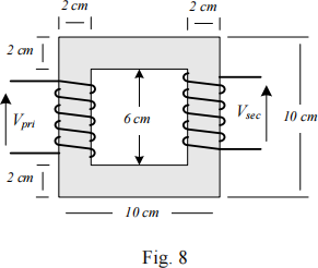
The dimensions of a 60 Hz step-down transformer are shown in Fig. 8. The cross section of the core is 2 cm × 2 cm. It made of laminated silicon steel with a relative permeability of 2000. According to the nameplate, the apparent power is 250 VA, the primary voltage is 110 Vac and the secondary voltage is 12 Vac . In the open circuit test, 0.01 A input current is measured. The input power is too small and it can be ignored.
(1) Find the magnetizing inductance and the reluctance of the transformer.
(2) Starting from Faraday’s law, derive the inductance of primary winding in terms of number of turns and reluctance.
(3) Determine the number of turns in the primary and secondary windings.
(4) Show that the maximum flux density is below 0.5 Tesla.
Solution
![]() X = Voc = 110 = 11 × 103 Ω L = Xm = 11 × 103 = 29. 18H
X = Voc = 110 = 11 × 103 Ω L = Xm = 11 × 103 = 29. 18H
1)
l 4 × 0.08
![]() core µo × µr × Ae
core µo × µr × Ae ![]()
2) v = N ![]() ---(1), Ni = φℜ ---(2) ,Substituting (2) into (1) get v =
---(1), Ni = φℜ ---(2) ,Substituting (2) into (1) get v = ![]()
![]() = L
= L ![]() , L =
, L = ![]()
3) N = ![]() Lℜ =
Lℜ = ![]() 29. 18 × 318310 = 3047.67 = 3048 Turns
29. 18 × 318310 = 3047.67 = 3048 Turns
,
a = ![]() = 9. 17, Ns = 3048 / a = 332.39 = 333 Turns
= 9. 17, Ns = 3048 / a = 332.39 = 333 Turns
4) B = φmax = NIpk = 3048 × 0.01 × ![]() = 0.339 T
= 0.339 T
![]() max A ℜA 318310 × 0.022
max A ℜA 318310 × 0.022
2023-06-27