Phys127AL, Spring 2023, Homework 3 solutions
Hello, dear friend, you can consult us at any time if you have any questions, add WeChat: daixieit
Phys127AL, Spring 2023, Homework 3 solutions
1). Design a circuit that will cause a constant 1 mA of current to flow through a variable resistor, even as the resistance value changes over a range from 1k to 5k. Make sure that the choice of circuit values provides constant current over that resistance range.
We can do that with the circuit described in class, where we bias the base to set the emitter voltage and then the emitter resistor sets IE ≈ IC regardless of the value of the collector resistor, which will be our load resistor RL . That is shown in the circuit below.

To get 1 mA of emitter current, we can set VE = 1 V and RE = 1k so that

This requires biasing the base to 1.6 V (VB ≈ VE + 0. 6 in active mode), which we can do with R2 = 16k and R3 = 84k for VCC = +10 V.
The collector current is the same as the emitter current due to the transistor rule that IC = IE + IB ≈ IE . As the load resistor increases the voltage drop across the collector resistor increases and the voltage drop across the transistor reduces to compensate. However, the voltage drop across the transistor needs to be at least 0.2 volts to satisfy the rule that VC > VE + 0 .2 (to be still within active mode instead of saturation mode) . When the load resistance reaches the maximum of the specified range, RL = 5k, VC reduces to 5 volts, which is still within that specification .
2). Explain the function of the circuit in the attached breadboard cartoon (some elements of the full circuit are missing that you should be able to fill in based on your experience and lecture). Be quantitative in your explanation (we get to use the color codes!).

We begin by recognizing an NPN transistor with the input signal going to the base and the output signal coming from the collector, so this is a common emitter amplifier. The rows of pins at the bottom of the picture must be the positive and negative power supplies, which is how you commonly set up things on the breadboard in lab. The actual power supply connections or values are not shown, but we can easily tell that the red wire is the positive supply, and the black wire is the negative one. Based on the input biasing network we can also tell that the negative supply is ground rather than a negative voltage (if could also be a negative voltage, but remember the purpose of the voltage divider and the use of an input capacitor to deliver AC signal).
The input biasing has a resistor with color bands of Brown-Brown-Red to the positive supply and Brown-Black-Red to the negative supply. These correspond to 1.1kΩ and 1kΩ . Since they are approximately equal, it seems reasonable that the negative supply is ground and the input is being biased halfway between ground and the positive supply. So, the circuit diagram is

Where we can use the resistor color bands to determine the following:
• R1 = Brown-Black-Red = 1k
• R2 = Brown-Brown-Red = 1. 1k
• RE = Yellow-Violet-Brown = 470
• RC = Yellow-Violet-Red = 4.7k
The gain of the amplifier is then G = −RC/RE = −10.
Finally, we can estimate the capacitance values by recognizing that these are physically large, electrolytic capacitors, so they must have values of 10 to 100 uF. If you are not familiar enough to recognize a specific component, you can also just search through capacitors in an online supplier to estimate the order of magnitude. Once we know that C1 ≈ C2 ≈ 10uF, we can estimate the 3dB point of the circuit using R = 500 from the input impedance of the biasing network (effectively the 1.1 k and 1 k Ohms resistors in parallel, refer to textbook section 4.9 if unsure how the 3dB frequency is calculated for common emitter amplifier circuit). That is

This indicates that this is a ×10 audio amplifier (works for audio frequency signals, for reference, the commonly used radio amplifier, RF amplifier, works typically in the range 10 kHz
to 1 THz).
Note that it is a good skill to be able to just look at a circuit and figure out most ofwhat it does. If you want to challenge yourself, think about what small modification you could make to turn this into a times 20 audio amplifier.
3). Answer the following questions for this circuit.
(a) What is the input impedance at high frequencies?
(b) What is the DC bias level of Vout.
(c) Write an expression for vout(t) in terms of vin (t) .
(Note the lower case letters, representing changes)
(d) Write an expression for Vout(t) in terms of Vin(t) .
(Note the upper case letters).

(a) At high frequency the input capacitor acts as a short and we are left with the biasing network in parallel with βRE. So,
Xin = 10k || 100k || β*1k ≈ 10k
(b) We can calculate Vout as follows.
Vout = VCC − ICRC = VCC − (VE/RE)RC = VCC – [(VB − 0.6)/RE]RC
The base voltage is set by the biasing network:
VB = VCC ![]() = VCC/11
= VCC/11
So
Vout = VCC – [(VCC/11 − 0.6)/RE]RC
Plugging in the values we get
Vout = 15 – [(15/11 − 0 .6)/1k]*10k = 15 − 7 .6 = 7.4V
(c) The lowercase v corresponds to the change in the voltage (or commonly referred to as the AC component of a signal), which is just the simple gain relationship as long as there is no clipping (when the circuit is still in active mode) . So,
RC
vout(t) = −vin(t)
RE
(d) The uppercase V corresponds to the full voltage, DC and AC combined, so Vout is the total voltage at output terminal, while Vin is effectively just vin , as the input capacitor removes any DC offset from the input, leaving only vin(t) . This results in adding the DC quiescent value calculated in (b) and the AC part from (c). So,
RC
Vout(t) = 7.4 − vin(t)
RE![]()
4). Design a transistor-based circuit to generate two copies of an input signal that are both the same amplitude as the input, with one having the same sign as the input and the other being inverted. (This could then be used to drive a differential input to a twisted pair transmission line)
This circuit will do the job.
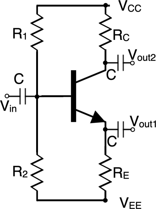
Vout1 would be the signal with the same sign (the follower), while Vout2 would be the opposite sign counterpart. The resistance values RE and RC needs to be the same to have a unity gain.
2023-06-17