Physics 127AL, Quiz 1 Solutions
Hello, dear friend, you can consult us at any time if you have any questions, add WeChat: daixieit
Physics 127AL, Quiz 1 Solutions
Thursday 4/27
You have 15 minutes
1. Examine the following circuits:
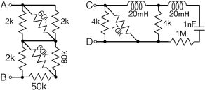
1a. (5 points) Approximate to within 10% the impedance between points A and B for a DC signal.
1b. (5 points) Approximate to within 10% the impedance between points C and D for a DC signal.
1c. (5 points) Approximate to within 10% the impedance between points C and D for a signal with a frequency of 60 Hz.
1. Solution
1a. The circuit has two sections in series. The first section has three resistors in parallel - the 60k can be neglected in parallel, leaving two 2k resistors that add in parallel to make a single 1k equivalent resistor. The second section is 2 k in parallel with combinations of (60k || 80 k) + 50k, and so reduces to just 2k. We then add 1k and 2k to get a total of 3k for the circuit. Full credit if within 10%, zero otherwise
1b. For DC signals, the capacitor impedance goes to infinity (xC = 1/aC) and the inductor impedance is zero (xL = aL). So the right hand capacitor is open and not relevant, and the inductors are shorts. The remainder is a 4k, 4k, and 70k resistor in parallel. We neglect the 70k (at 10%) and add the two 4k resistors in parallel for a total of 2k. Full credit if within 10%, zero otherwise
1c. At 60 Hz, a = 2mf ~ 6 x 60 ~ 360. The impedance of the capacitor is xC = 1/aC ~ 1/(360 x 10 −9 ) which is a big number and can be treated as infinite again. The impedance of the inductor is xL = aL ~ 360 x 20 x 10 −3 ~ 7 which is small and can still be treated as a short. So the answer here is the same as part 1b, 2k. Full credit if within 10%, half credit if wrong answer but correct attempt at understanding the capacitive and inductive impedances.
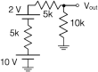
2. (5 points) Find the Thevenin equivalent of this circuit
2. Solution
We can collect all the elements into a single 12 V battery going into a voltage divider with R1 = R2 = 10k. By memory for the Thevenin equivalent of a voltage divider, or by looking at the open and short circuited outputs and calculating that way, we can write down the answer: vTh = 6 V (the open circuit voltage) and RTh = 5k (the open circuit voltage divided by the short circuit current, or the output impedance of the voltage divider). Half credit for each.
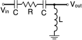
3. (5 points) Describe the frequency response for this circuit in words. (Component values are not given, so your description does not need to include specific numbers, just the overall behavior.)
3. Solution
Short answer - it’s a high pass filter (just that sentence would receive full credit). Longer answer - at low frequencies, the C is open and the L is a short - that forces vout → 0 from both sides. At high frequencies, C is a short, and L is open, so vout → vin, again for lots of reasons. A high pass filter. Full credit if recognized as high pass filter. Half credit if correct recognition of C and L behavior, but not as a high pass filter.
2023-06-15