Assignment for HVDC & FACTS module
Hello, dear friend, you can consult us at any time if you have any questions, add WeChat: daixieit
MSc in Electrical Power Systems
Assignment for HVDC & FACTS module
Introduction: This assignment is to
• Gain understanding of FACTS device - STATCOM and its functionalities by literature review;
• Build detailed power flow models for STATCOM;
• Carry out case studies to understand the control performance ofthe STATCOM and hence make comparisons of results of different cases;
• Draw conclusions and provide recommendations based on your studies.
The assignment deadline is available on Canvas. This assignment represents 50% of the assessment.
(Newton-Raphson Power Flow Solution with FACTS Devices)
Consider a two-bus system with the single-line diagram shown in Fig. 2. In the two-bus system:
• Bus 1 is slack bus where voltage is given: V1 = 1.05 + j0.0 p. u.
• A load Pd2 + jQd2 = 0.8 + j0.25 p. u.. is connected at Bus 2.
• The impedance of the transmission line between bus 1 and bus 2 is Z12 = 0.0 + j0.15 p.u.
• A STATCOM is connected at bus 2 through a transformer regulate the bus 2 voltage to be constant value.
• The impedance of the STATCOM transformer is Zsh = 0.0 + j0.10 p. u..
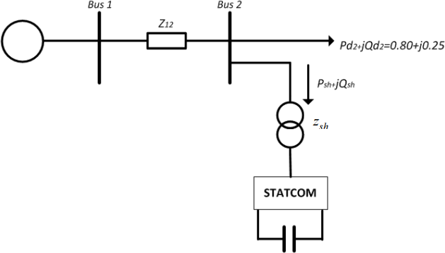
Fig. 2 Two-bus system with STATCOM
You are asked code computer programme (in MATLAB) using Newton-Raphson method to calculate power flow solutions, using a convergence tolerance of eP = 10-6 : max(| DPik |, |DQi(k) |) ≤ eP where k is the number of iterations. With the computer code developed, the following case studies will need to be carried out:
Q1 (Case 0): The STATCOM is NOT connected at bus 2, show the mathematical model using Newton- Raphson method and the power flow solution including
(a) bus voltages at Bus 1 and Bus 2 (in polar coordinates in terms of voltage magnitudes and voltage angles).
(b) active power flow and reactive power flow P12 + jQ12 and P21 + jQ21 .
Q2 (Case 1): The STATCOM connected at bus 2 is to regulate the bus 2 voltage magnitude to be 1.05 p.u., show the mathematical model using Newton-Raphson method in polar coordinates and the power flow solution including
(a) bus voltages at Bus 1 and Bus 2 as well as voltage of the STATCOM (in polar coordinates in terms of voltage magnitudes and voltage angles).
(b) active power flow and reactive power flow P12 + jQ12 and P21 + jQ21 .
Q3 (Case 2 and Case 3): For the problem in Q1, if the STATCOM connected at bus 2 is to regulate the bus 2 voltage magnitude to be 1.07 p.u. (Case 2) and 1.03 p.u. (Case 3), respectively, please show the power flow solutions for Case 2 and Case 3, respectively, and compare them with the power flow solution in Q1 (Case 1). The power flow solution should include:
(a) bus voltages at Bus 1 and Bus 2 as well as voltage of the STATCOM (in polar coordinates in terms of voltage magnitudes and voltage angles).
(b) active power flow and reactive power flow P#2 + jQ#2 and P2# + jQ2# .
Q4 (Case 4 and Case 5): For the problem in Q2, the impedance of the transmission line between bus 1 and bus 2 is changed into Z#2 = 0.0 + j0.20 p.u., Case 4 and Case 5 are corresponding to Case 2 and Case 3, respectively. Please show the power flow solutions for Case 4 and Case 5, respectively, and compare them with the power flow solutions for Case 2 and Case 3, respectively. The power flow solution should include:
(a) bus voltages at Bus 1 and Bus 2 as well as voltage of the STATCOM (in polar coordinates in terms of voltage magnitudes and voltage angles).
(b) active power flow and reactive power flow P#2 + jQ#2 and P2# + jQ2# .
Report Structure: Based on the above assignment, you are asked to prepare a report of around 20 pages including the following sections:
1. Cover page (Please use the cover page template available on Canvas)
2. Abstract
3. Table of content
4. Introduction:
• Providing comprehensive understanding of STATCOM and its functionalities by literature review;
• Showing the contributions of this report;
• Showing the arrangement or structure of the report.
5. Detailed Mathematical modelling of FACTS device, i.e., STATCOM including Power Mismatch equations, Newton Raphson solution (Jacobian Matrix and Updating equations) in Polar Coordinates. Necessary diagrams should be included.
6. Calculation results using the MATLAB code and discuss the results and make comparisons of the different cases. For each Case, by using the Newton-Raphson method in Polar Coordinates, show the convergence characteristics by drawing a relationship: maX (| DPik |, |DQi(k) |) vs iteration count k where i is bus number.
7. Conclusions
8. References (IEEEformat should be used)
IEEE Journal Paper Word Template can be found here: https://www.ieee-pes.org/templates-and- sample-of-pes-technical-papers
9. Appendix
Test system and related data, complicated derivations, as well as computer code can be included into Appendix.
Report Layout: Page numbers should be inserted at the bottom centre of each page except the cover page. Report should be typed on A4 paper, spaced 1.5 with margins as follows: Top-2.54cm, bottom- 2.54cm, left-2.54cm, right-2.54cm. Font size of 11 or 12 can be used.
Report Writing: The style of writing should be formal and precise with no more words than needed to make the meaning clear. Every statement must be justified, and nothing that is written should be vague. Tables and diagrams should be used wherever appropriate. A specific point that must be made is that the report should be written in the third person. For example, ‘this was carried out’ should be used rather than ‘I did this’ . This is the traditional method of expression used in scientific and technical writing.
Marking Criteria: The following is the marking criteria for this assignment:
(1) Abstract, Table of Contents, Introduction (10%) (a) Abstract
a short summary of your report, usually about a paragraph (less than 100 words) long. A well-written abstract serves multiple purposes:
• an abstract lets readers get the gist or essence of your report quickly, in order to decide whether to read the full report;
• an abstract prepares readers to follow the detailed information, analyses, and arguments in your full report;
• and, later, an abstract helps readers remember key points from your report.
(b) Introduction: a general description of the problem to be solved.
(2) Theory and Methodologies: how the problems are solved and related theories (20%).
(3) Results and discussions (40%)
• Showing results of different cases
• Comparing results of cases
• Showing computer code (in a separate .m file or .m files)
(4) Conclusions (10%).
(5) Use of references (5%)
(6) Overall report quality and structure (15%)
Recommended References for the completion of the assignment:
1. PPT lecture notes of HVDC AND FACTS and PSOC (Power Flow)
2. Xiao-Ping Zhang, Christian Rehtanz, Bikash Pal, Flexible AC Transmission Systems: Modelling and Control, 2nd ed, ISBN 978-3-642-28241-6, 2012, e-Book (electronic version is available from the University of Birmingham Library), Chapter 2.
3. W. F. Tinney and C. E. Hart, "Power Flow Solution by Newton's Method," IEEE Transactions on Power Apparatus and Systems, vol. PAS-86, no. 11, pp. 1449-1460, Nov. 1967, doi: 10.1109/TPAS.1967.291823.
Plagiarism: Plagiarism will not be tolerated. It is the act of a Student claiming as their own, intentionally or by omission, work which was not done by that Student. Plagiarism also includes a Student deliberately claiming to have done work submitted by the Student for assessment which was never undertaken by that Student, including self-plagiarism and the other breaches. Sanctions of a plagiarism include the Student failing the Programme of study.
Submissions: The report as well as the MATLAB code (.m file) will need to be submitted via the Canvas. Please do not submit .zip files. Submit .pdf or word file for the report, and .m file or .m files for MATLAB codes (you could have more than one .m files).
2023-04-24