ELEC9713 Industrial and Commercial Power System Assignment 2023S1
Hello, dear friend, you can consult us at any time if you have any questions, add WeChat: daixieit
Assignment 2023S1
ELEC9713 Industrial and Commercial Power System
Lecturer: Dr. Daming Zhang, Email:daming.zhang@unsw.edu.au.
This assignment is due on Sunday midnight of week 9 (16/April/2023). The assignment needs to be submitted via Moodle as a pdf file.
The assignment must be submitted individually and must be your own work. The UNSW policy on student plagiarism can be found on the www.unsw.edu.au website. Note that UNSW uses automated plagiarism-checking software.
The assignment will be marked out of 20. Note that late submission without good reason will see you lose significant marks.
A power supply system is designed for a new building with four groups of loads as shown in Fig. 1, where there are three sources located at bus 1, bus 5 and bus 4B respectively. Power of sources 1 and 2 is from synchronous generator based sources while power from bus 4B is from PV panels based generation.
The ratings of each transformer are as follows:
Transformer T1 : 5.2MVA, 11kV ∆/415V Y;
Transformer T2 : 5.2MVA, 11kV ∆/415V Y;
Transformer T3 : 1.0MW, 2.2kV Y /11kV ∆ .
The ratings of balanced three-phase loads for each of four groups are given below:
Load group 1: 1.2MVA, 415V, a power factor of 0.95 lagging;
Load group 2: 1.0MVA, 415V, a power factor of 0.975 lagging;
Load group 3: 1.05MVA, 415V, a power factor of 0.94 lagging;
Load group 4: 1.05MVA, 415V, a power factor of 0.96 lagging.
Besides balanced three-phase loads, there are also single-phase loads for each of four groups.

Figure 1 Power supply system for a new building
Two identical transformer rooms are built to accommodate each of the two transformers T1 and T2 . Each of them has dimensions of 9.0m (length) X 9.0m (width) X 4.5m (height).

Figure 2 Top view of the transformer room with lightning protection rods
a) Four identical rods are planted symmetrically as shown in Fig. 2 to reach the target of lightning protection of the transformer rooms. Assume that lightning protection level II is adopted in this design. Use rolling sphere method to determine the minimum height of each rod. Discuss other possible lightning interception methods for the transformer room besides the approach of using four vertical rods. (Marks: 20%)
b) Describe lightning protection system for the overhead transmission lines between bus 5 and bus 6. Sketch a diagram to facilitate your description. (Marks: 10%)
c) Describe the whole lightning protection system for the new building in which four groups of loads are located. (Marks: 10%)
d) Describe a feasible lightning protection for the solar panel system. Assume that PV panels are supported by short poles in open space. (Marks: 8%)
e) List down basic criteria when choosing switchboards for each of the four groups of loads in the new building. (Marks: 10%)
f) Assume that source 1 is under maintenance. Breakers C1B through C10B are opened and tie breaker also stays open. Power to all the loads is from source 2 and PV panels. With phase-a voltage at bus 8 taken as reference phasor with its angle equal to zero degrees, the currents into each of the four loads are as follows:
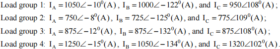
Calculate the neutral current in transformer T1 . Also calculate the line currents flowing through the primary side of T1 . Ignore the currents in the shunt branch of the transformer. Analyze the sequence components of the line currents at both sides of the transformer.
Assume that the voltage at bus 8 is kept at 415V. (Marks: 18%)
g) For the operation of f), PV panel produces balanced 400kW and 50kVAr lagging. The negative-sequence current compensator can effectively cancel negative-sequence components of the line currents at the primary or ∆ side of T 1 . Calculate three-phase currents from source 2 through the overhead lines. (Marks: 9%)
h) With the source 1 back to service, load groups 3 and 4 are planned to connect back to source 1. Discuss the operation steps to achieve this change. (Marks: 10%)
i) Discuss how to use proper measures to reduce the transient voltage rising rate across motors in the building. (Marks: 5%)
2023-04-15