ELEN90074 Introduction to Power Engineering
Hello, dear friend, you can consult us at any time if you have any questions, add WeChat: daixieit
ELEN90074 Introduction to Power Engineering
Mid-Semester Exam, Sem. 1, 2022
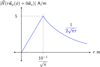
Figure 1: Magnetic field strength in Q1(b).
![]()
![]() Q1 (5 marks) Consider a solid conducting wire that extends along the z-axis of a cylindrical co- ordinate system. The origin of this co-ordinate system is located at the centre of the circular wire cross-section, at a point that is far away from both ends (i.e., the wire is long). The radius of the cross-section is b = (1/^π ) . 10 − 1 m, and the conductor carries current I = ^π A in the
Q1 (5 marks) Consider a solid conducting wire that extends along the z-axis of a cylindrical co- ordinate system. The origin of this co-ordinate system is located at the centre of the circular wire cross-section, at a point that is far away from both ends (i.e., the wire is long). The radius of the cross-section is b = (1/^π ) . 10 − 1 m, and the conductor carries current I = ^π A in the ![]() z direction. It may be assumed that the current density J- is uniform across the conductor cross- section, and that the magnetic field is cylindrically symmetric for lzl < 1.
z direction. It may be assumed that the current density J- is uniform across the conductor cross- section, and that the magnetic field is cylindrically symmetric for lzl < 1.
![]() In Gradescope, upload no more than 2 A4 pages with clearly labelled responses to the following: (a) Show that J-(r
In Gradescope, upload no more than 2 A4 pages with clearly labelled responses to the following: (a) Show that J-(r![]() ρ (φ) + 0
ρ (φ) + 0![]() z ) = 100^π
z ) = 100^π ![]() z A/m2 for 0 < r < b and φ e [0, 2π)? [1 mark] (b) Use V x
z A/m2 for 0 < r < b and φ e [0, 2π)? [1 mark] (b) Use V x ![]() = J- and Stokes’ Theorem, to show that for all φ e [0, 2π), the magnitude of the magnetic field strength
= J- and Stokes’ Theorem, to show that for all φ e [0, 2π), the magnitude of the magnetic field strength ![]() (r
(r![]() ρ (φ) + 0
ρ (φ) + 0![]() z ) A/m varies as shown in Figure 1. [4 marks]
z ) A/m varies as shown in Figure 1. [4 marks]
Q2 (7 marks) A length é m rigid bar of small cross-section and very high conductivity lies in the z = 0 plane. One end is fixed at the origin, and the rest of the bar is free to rotate about the z-axis in this plane with no friction. Consider a steady state with the bar rotating at (slow) constant angular velocity ω- = ω0 ![]() z rad/s, for given ω0 > 0, in the presence of a spatially uniform impressed
z rad/s, for given ω0 > 0, in the presence of a spatially uniform impressed
magnetic flux density ![]() = B0
= B0 ![]() z Wb/m2 , for given B0 > 0. In this steady state, there is a fixed spatial distribution of conduction charge along the bar, and zero current density throughout. In Gradescope, upload no more than 2 A4 pages with clearly labelled responses to the following:
z Wb/m2 , for given B0 > 0. In this steady state, there is a fixed spatial distribution of conduction charge along the bar, and zero current density throughout. In Gradescope, upload no more than 2 A4 pages with clearly labelled responses to the following:
(a) Let φ(t) = ω0t + φ0 be the angular position of the bar at time t > 0. Show that the induced electric field ![]() I (t, r) = B0 ω0r
I (t, r) = B0 ω0r ![]() ρ (φ(t)) N/C at the point r
ρ (φ(t)) N/C at the point r ![]() ρ (φ(t)) + 0
ρ (φ(t)) + 0![]() z inside the bar,
z inside the bar,
0 < r < é . [2 marks]
(b) What is the electric potential difference between the two ends of the bar, at é![]() ρ (φ(t)) + 0
ρ (φ(t)) + 0![]() z and at the origin, respectively? Which end has the higher potential? [2 marks]
z and at the origin, respectively? Which end has the higher potential? [2 marks]
(c) To maintain the specified steady state, what net external torque is required? [1 mark]
(d) With the net external torque unchanged from part (c), and considering the very high conduc- tivity of the bar, qualitatively describe what would happen if the impressed magnetic field abruptly changed sign to become ![]() = _B0
= _B0 ![]() z . Comment on the time it takes to recover a steady state, and its characteristics after the change relative to before the change. [2 marks]
z . Comment on the time it takes to recover a steady state, and its characteristics after the change relative to before the change. [2 marks]![]()
Q3 (5 marks) Figure 2 (on page 4) shows a two part ferromagnetic core, with an insulated copper winding that makes N turns around the inner part, which is supported axially in a way not shown. The inner dimensions are such that the height g m of the narrow air gaps is much less than the width w m, which is much less than the depth d m. Take the permeability of air to be µ0 and the core permeability to be µ s o. The winding carries current I A. The leakage of flux outside of the core is negligible.
In Gradescope, upload no more than 1 A4 page with clearly labelled responses to the following:
(a) Explain why the magnitude of the magnetic field strength in the air gaps is approximately
l ![]() gap l s NI\(2g) A/m. [2 marks]
gap l s NI\(2g) A/m. [2 marks]
(b) What is the magnetic flux across the air gap through the top of the inner part? [1 mark]
(c) What is the self inductance of the winding? [2 marks]
Q4 (8 marks) To make a transformer, an insulated secondary copper winding with 2N turns is added
to the inner core in Figure 2. Since there is negligible leakage flux, winding conduction losses dominate. The corresponding sinusoidal steady-state circuit model is shown in the top part of Figure 3 (on page 4), where the boldface symbols are phasor representations of the corresponding currents, voltages, and impedances (i.e., these are complex numbers.) In the model, Rs = 2Rp . In Gradescope, upload no more than 2 A4 pages with clearly labelled responses to the following:
(a) How are Ep , Es , Il , and Is related in the top circuit model shown in Figure 3? [1 mark]
(b) Find R and Zp to make the two circuits shown in Figure 3 equivalent. [2 marks]
(c) Draw a phasor diagram relating Vp , Il , and Vl for the bottom circuit in Figure 3. [2 marks]
(d) Taking Z = lZlejφ to be the full load impedance, show that the transformer voltage regulation performance is
(lVs,nIl _ lVs,ll)/lVs,ll =╱′1 + 12 cos(φ)Rp /lZl + 36(Rp /lZl)2 _ 1、
where ‘l’ denotes full load, and ‘nI ’ no load, with the same lVp l in both cases. [3 marks]
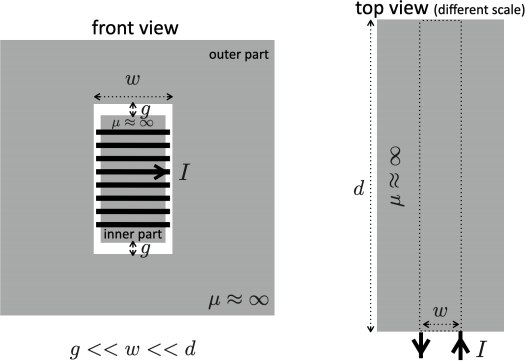
Figure 2: Wound ferromagnetic core in Q3 and Q4.
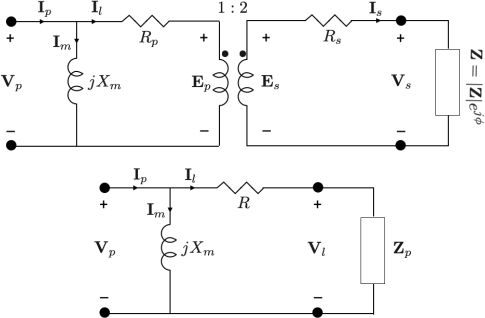
Figure 3: Transformer circuit models for Q4.
2023-04-14