MME 412: Advanced Mechanics of Materials Spring 2023
Hello, dear friend, you can consult us at any time if you have any questions, add WeChat: daixieit
Computational Assignment # 2
MME 412: Advanced Mechanics of Materials
Spring 2023
Background/Application
Tapered structures or structures with non-uniform cross sections are very efficient at minimizing stresses, structure weight, and material cost. Examples of tapered structures both natural and artificial are shown in the figure below.
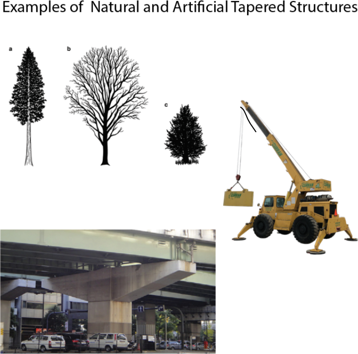
Figure 1: Examples of natural and artificial tapered structures
You and another classmate have been hired as entry-level engineers at a small structural engineering firm. Your firm often tries to build unique structures that have varying cross-sectional area throughout their length to minimize weight and to produce aesthetically pleasing shapes. To help them evaluate stresses and deflections within simple tapered structures, you and your partner are asked to develop a MATLAB ® code that applies finite element analysis to these structures. As an initial exercise, you are starting off with a very simple structure, a tapered rod in tension, to validate your code. This geometry was chosen so you may validate your findings using an alternate analysis method (Castigliano’s Method). A senior engineer has prescribed the task in further detail (see suggested Methods/process for the assignment).
Purpose of the Assignment
To apply your understanding of Castigliano’s Method and FEA to solve for the deflection and stress within a tapered beam. Experience with both methods should give students confidence that they could apply both methods in structures with non-uniform geometries.
Audience for the Computational Assignment
You and your partner are reporting your results back to the senior engineer (MS in Mechanical Engineering). She is managing multiple entry level engineers so please lay out your analysis as succinctly as possible without leaving out any major steps.
Suggested Methods/Process for the report
For each part of the report, please use bullet points or numbered lists to explain and support your calculations with essential equations. This format would aid the senior engineer review your work quickly.
Initial Information
A tapered round aluminum bar (E=70 GPa, Sy=276 MPa) is clamped at its small end and a constant load, F, is applied at the free end. The geometry of the beam is shown below:
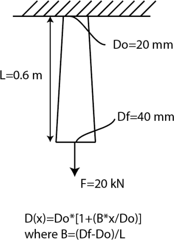
(Note: Please refer to Lectures 11 & 12 (Castigliano’s Method) and Lectures 14-16 (FEM) for help with this assignment. You may edit the code from Lecture 16)
Part a)
Using Castigliano’s Method, you and your partner should determine the deflection at the free end of the bar. To check and see if your Castigliano’s method is close to correct, you may estimate the bounds of the deflection using Hooke’s Law. For example, you could find the deflection of a uniform bar with diameter Df and the the deflection of a uniform bar of diameter Do. Your solution for deflection from Castigliano’s method should be in-between the values obtained from Hooke’s Law for Do and Df.
Part b)
Using Finite Element Method, determine the deflection at the free end of the bar. Please describe in this section how you and your partner defined the stiffness matrix of each bar element and the necessary boundary conditions you used to help solve the problem.
Part c)
Calculate the percent error between the exact solution you found using Castligano’s method (part a) and the approximate FEM solution (part b). The percent error between your two solutions should be created as a function of the number of elements you used in your group’s FEM calculation.
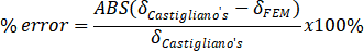
You and your partner must be able to vary the number of elements in your FEM code and store the results of the deflection at the end of the beam for each iteration to create the plot.
Part d)
Determine the minimum number of elements required to achieve a percent error of <0.01% between the FEM solution and Castigliano’s method solution. Please explicitly state the minimum number of elements required in the body of the report. This should be very easy to find using the graph your group made in part c.
Part e)
Plot the axial stress within the bar along the length (from the base of the bar to the free end where the load is applied). For this plot, use the of minimum number of elements required to achieve a percent error of <0.01% you found in part d. Explicitly state how you calculated the stress within each element within your report.
Appendix)
Create an appendix in the report with the MATLAB Finite Element code. Please make comments in the code that would guide the reader to the function of each section of the code. Ideally, this code could be quickly modified and used by another member of the company if needed.
Due Date
The Computational Assignment is due on 3/28 at 6:00 PM. This assignment should be completed individually for students in MME 512 and in pairs for MME 412 students.
2023-03-16