EE6307 CA1: Continuous-Time Filters Semester 2, 2022-2023
Hello, dear friend, you can consult us at any time if you have any questions, add WeChat: daixieit
EE6307 CA1: Continuous-Time Filters
Semester 2, 2022-2023
1. Using large-signal saturation model equation of MOSFET to derive the large-signal output current expression of Fig. 1. The transconductance parameters for M1 and M2 are k1 = ![]() and for M3 and M4 are k2 =
and for M3 and M4 are k2 = ![]() respectively. State your assumptions.
respectively. State your assumptions.

Figure 1
Draw and explain the improved transconductor that can further enhance the input signal handling capability.
2. Design a MOSFET-C fully-balanced filter based on the continuous-time filter prototype as shown in Fig. 1. Determine the unknown component values in the filter prototype at nominal cut-off frequency. In the MOSFET-C filter design, find the tuning range of the control signal on the MOSFET-C filter and all the channel lengths for MOSFET resistors. State the assumptions. The specifications of the MOSFET-C filter are given as follows:
• Low-pass Butterworth response
• Q= 0.707, DC gain H0 = 0 dB
• C1 = C2 = 20 pF
• Channel width of MOSFET devices = 5![]() m
m
• Tuning range +/- 25% from nominal, with minimum 200mV for over-design margin for control voltage VC
• Cut-off Frequency fo = 10 kHz
• Maximum Signal = 200 mVpeak
• Supply = +/- 5V
• All p-channel devices
It is given that the p-channel MOS transistor process parameters are as follows
μpCox = 30 μA/V2
Vtp = -0.9 V
γ = 0.5 V1/2
Cox = 1.9 x 10⁻³ pF / (μm)2
20F = 0.7V
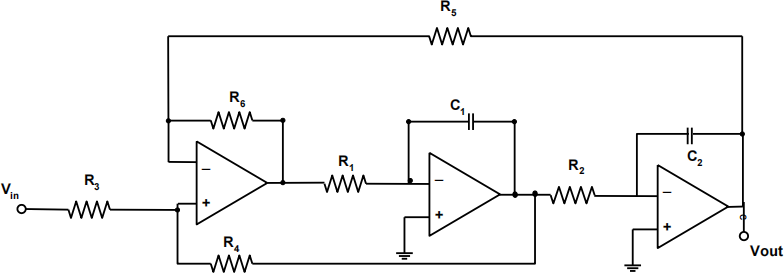
Figure 2
2023-03-10