COMP 3490 Computer Graphics 1 Assignment 2 Winter 2023
Hello, dear friend, you can consult us at any time if you have any questions, add WeChat: daixieit
COMP 3490 Assignment 2
Winter 2023
Due date and submission instructions. Submit one zip file containing all of the pde files required to run your submission. Divide these files into two subfolders: one containing your submission for Ques- tions 1-3, and the other containing your submission for Question 4. Name your zip file in the style of VaughanJenniferA2.zip. All submissions should be uploaded to the Assignment 2 folder on UM Learn by 11:59pm on Friday March 10.
Questions 1 - 3: The 2D Pipeline
Getting started. Read these instructions all the way through. Then read the supplied template code. There are several drawing modes that you need to implement, and function stubs that you need to complete.
The purpose of these questions is for you to build your own version of the 2D transformation pipeline, using the files in A2Template .zip as a starting point. You may not use any of Processing’s built-in pro- jection or transformation commands such as ortho(), rotate(), translate(), scale(), pushMatrix(), popMatrix(), etc. You must write your own versions of all of these functions. You can only use vertex() in the one place mentioned in the code (see Question 1).
You will also use hierarchical modeling to draw a scene. For your drawing, you will use Processing’s built-in beginShape()/endShape() functions, together with your own myVertex() command and the transformation pipeline that you built.
Vectors and Matrices. You will use the PVector class (see here) and the PMatrix2D class (see here). All of the PVector methods are fine to use, though you should not need very many of them. PMatrix2D methods that implement basic arithmetic or allow you to make copies are also fine to use: my solution code uses apply(), get(), mult(), and reset(). See Question 2 for the one place where you are allowed to use invert().
Question 4: 3D Rotations
This question is independent of the others and will be written in its own file(s). No initial code is supplied: you get to design everything. You can use Processing’s P3D renderer, and any of the commands perspective(), frustum(), or camera(). You can also use Processing’s matrix stack and commands for manipulating it such as pushMatrix()/popMatrix() and translate(), rotate() or scale(). To draw objects in 3D space, you will need beginShape()/endShape() and vertex(). Finally, you can use the PVector and PMatrix3D classes (see here for the PMatrix3D documentation).
Coding standards
Your code will be read, and you should write it with that in mind. Use reasonable variable and function names, and avoid magic numbers. Poor style may result in lost marks.
Code will be tested with Processing 4.1.1. Code that does not compile, that does not run, or that crashes often enough that it is difficult to test will receive a score of 0.
For Questions 1 - 3, you must complete the function stubs provided in the template. Your code must implement all of the hotkeys set up in the template. You can and should add new functions and global variables as needed. Some global variables are explicitly suggested in the text, but this is not a complete list; you will probably find that you need others. You can add new classes if you wish, particularly for use in drawing your scene.
Questions
1. Implement the Transformation Pipeline (13 marks)
You will implement the full transformation pipeline, beginning with a vertex coordinate in object space and ending with its corresponding coordinate in viewport space. To mimic OpenGL Immediate mode, you will make the following global, stateful matrices to carry out the different transformations.
❼ Vp - the viewport matrix. Transform from NDC to the Processing viewport. Remember that the
Processing viewport coordinates are set up so that the origin is at the upper left corner of the canvas, the +x-direction is to the right, and the +y-direction is downward.
Use the function getViewport() to create and return the viewport matrix. Set up Vp once at the beginning of your program, and don’t touch it thereafter.
❼ Pr - the projection matrix. Transform from camera coordinates to NDC. Specifically, set up an
orthographic projection of the region in camera coordinates that is bounded by the parameters left, right, bottom, and top.
Use the function getOrtho() to create and return the projection matrix. You will call this function whenever you need to set up or change the projection. Several projection modes are given in the template. Make sure you implement and test them all.
❼ V - the view matrix. Transform from world coordinates to camera coordinates.
Use the function getCamera() to create and return the view matrix. You will call this function any time a camera parameter changes.
By default, set the camera so that its center is at (0, 0), its up vector is in the direction of the y-axis, and its perp vector is in the direction of the x-axis. The zoom parameter will be discussed in Question 2; to begin with, set it to 1.
❼ M - the model matrix. Transform from model coordinates to world coordinates.
For now, set this matrix to the identity. It will only be modified by the transformation functions that you will write in Question 3.
Each of the functions listed above can be found in the file Transforms2D .pde. The return type in each case is PMatrix2D. The only way that you should modify one of the global matrices Vp, Pr or V is by assigning it the return value from one of these function calls. Don’t write code within getOrtho(), getCamera() etc. that uses or modifies a global matrix.
Now complete the myVertex() function that is set up in Transforms2D .pde. Given a vertex v in object coordinates, myVertex computes
(Vp)(Pr)(V)(M)v
using the global matrices, and plots the result using the Processing vertex() command. Use a PMatrix2D method for matrix multiplication. Read the API carefully and make sure that you are multiplying on the correct side.
Comments.
❼ The key to this question is to come up with a reliable debugging strategy. Once you have
myVertex() implemented, start by initializing all of the transformation matrices to the identity. Draw a test pattern. Do the points appear where you expect them?
Then incorporate your calculation of Vp. This should allow you to give drawing commands in normalized device coordinates.
Finally, include Pr. (V and M don’t do anything yet.) Make sure you check that all of the projection modes work as expected.
❼ For this and future questions, it will probably be helpful to write functions that construct and
return the matrices corresponding to different transformations. For example, PMatrix2D scaleMatrix(float sx, float sy)
returns the matrix that scales the x and y directions by the given parameters.
(2 marks for viewport matrix; 2 marks for projection matrix; 2 marks for camera matrix; 2 marks for myVertex and transform pipeline; 5 marks for the test pattern rendering correctly in all 5 ortho modes, 1 mark each)
2. Advanced Camera Models (16 marks)
Now you will introduce the ability to change the camera model. The file DrawingModesA2 .pde contains the hotkeys that you need to implement. Add the appropriate code to keyPressed().
For this question, you should add global variables that track the center of the camera, its up and perp vectors, and the current zoom setting. (Although you can calculate the perp vector from the up vector, it is convenient to save both.)
Your getCamera() function receives the center, up and perp vectors and the zoom value as parameters, and calculates and returns the view matrix V. Implement each of the following effects by changing one or more of these parameters, then calling getCamera() to update V.
❼ Zoom in/out. Modify how much the camera scales the image. Zooming in should make the image
appear larger, and zooming out should make it appear smaller.
When you change the zoom, the effect should be centered on the origin in cameTa coordinates, not the world origin.
Make the changes to the zoom value multiplicative, rather than additive. That is, when you zoom in or out, multiply or divide the global zoom variable by a fixed constant, rather than adding or subtracting.
❼ Pan the camera by clicking and dragging the mouse.
Complete the mouseDragged() code so that it changes the camera’s center location. Note that the variables mouseX, mouseY, pMouseX and pmouseY are all measured in viewport coordinates, whereas the center of the camera is measured in world coordinates. You will need to do some coordinate system conversions, but do not use the PMatrix2D invert() method. This calculation can be done using proportions.
Make sure that panning and zooming work correctly together, and that panning works correctly in all of the projection modes. When you click and drag, the scene should move at just the right speed to keep up with the mouse movements, and this should remain true even when you zoom in or out. Your conversion from viewport to world measurements will depend on the projection mode and the current zoom value.
❼ Rotate the camera. Add another global variable to track the angle of rotation, and use it to
modify the camera’s up and perp vectors. The key KEY ROTATE CW should rotate the camera clockwise (left-handed), which means that the scene rotates counterclockwise (right-handed).
Now make rotating and panning work correctly together. Once you rotate the camera, the y direction in viewport coordinates no longer corresponds to the y direction in world coordinates. What direction should it be instead? (Hint: you should already have a vector that points in this direction!)
❼ The zoom that you implemented above is always centered on the origin in camera space. Now
add the ability to choose your own center. When you right-click the mouse, the point where you clicked will remain stationary while the rest of the scene zooms in around it.
To implement this, zoom in, and adjust the camera location so that the point beneath the mouse stays in the same position on the screen. This gets a bit tricky because you have to move the camera center in world coordinates. For this question only, you can use the PMatrix2D invert() method.
(3 marks for zoom; 5 marks for panning; 3 marks for rotation; 3 mark for panning and rotation working correctly together, 2 for right-click to zoom in place)
3. Hierarchical Modeling (13 marks)
Implement a global stack for the model matrix. Complete the following functions, which can all be found in Transforms2D .pde.
❼ void myPush() and void myPop() back up and restore the model matrix. Careful of deep versus
shallow copy.
❼ Each of the functions below creates the appropriate transformation matrix, and post-multiplies
it into the global model matrix M. That is, if M is the current model matrix and T is the matrix representing the transformation, then the effect of calling the function is to replace M by MT.
• void myRotate(float theta)
• void myScale(float sx, float sy)
• void myTranslate(float tx, float ty)
These functions do modify a global matrix, unlike the functions you wrote in Question 1.
Now use the matrix stack and your transformation functions to create a complex scene. You are allowed to use Processing’s built-in functions fill(), stroke(), and strokeWeight() for setting the colors of objects and lines. Your scene must have the following properties.
❼ Each draw function creates visual objects roughly within a 2 × 2 object space, with coordinates
ranging from (−1, −1) to (1, 1).
You can pass properties such as ratios or proportions, colors, number of subcomponents, etc. to your draw functions, but do not pass scales, angles, or positions as parameters. Instead, the code that calls a particular draw function should use transforms to resize, rotate and position it. Use myPush and myPop to support hierarchical modeling.
❼ Your scene needs to be at least three nested calls deep: one draw function applies one or more
transformations, then calls a second draw functions, which applies further transformations and calls a third (or more).
For emphasis: each function should draw its particular component of the scene within a 2 × 2 model space. The function one level up, which calls this one, can rescale, rotate and translate as needed.
❼ Your end result must include some complex, multi-stage object that is drawn at different positions,
angles and scales. For example, here is how I met that standard with my cat picture.

Be careful of accidentally using Processing’s scale(), translate(), rotate(), pushMatrix() or popMatrix() functions. They will not work at all with the coordinate systems you are using.
(5 marks for matrix stack and transformation functions; 8 marks for scene, including sufficient hierarchy levels, all transformations demonstrated, and all camera controls working correctly)
4. Write My Demo – Quaternion Rotation and Interpolation (8 marks)
Create a new file called Quaternions .pde. This file is separate from the main assignment template and should be put into its own folder. You are not given any initial code for this question. Start from the beginning and make whatever design choices you think are best. You can use all of the functions related to Processing’s built-in 3D pipeline (see page 1 for a list).
Your goal is to write a piece of demo code that uses quaternions to represent arbitrary rotations, and that shows quaternion interpolation. Your demo should use perspective projection. Here are the desired features.
❼ Draw a cube in the center of the screen. To make the rotation more vivid, give each face of the
cube a different color. The cube begins at rest. (You can make a different choice about where to position the camera than the one shown here.)

❼ Choose two axes of rotation, ⃗u and ⃗v. The ⃗u axis should be something simple, like a vertical line
through the center of the cube. The ⃗v axis should be visibly distinct from ⃗u.
❼ Pressing the space bar starts and stops rotation. The cube initially rotates about the axis ⃗u.

❼ Pressing the i key starts the interpolation. Set up a parameter t that ranges from 0 to 1. When
t = 0, the cube rotates about ⃗u. When t = 1, the cube rotates about ⃗v. Increment t by some small amount in each frame, and rotate the cube by the corresponding interpolated quaternion (see the mathematical remarks below). Pressing i again should pause the interpolation.
❼ Visualize the axes of rotation. Start by drawing a line that represents the axis ⃗u. Once the
interpolation starts, draw lines that represent the initial axis, the final axis, and the current axis.

❼ Pressing the r key resets the demo back to the beginning.![]()
Here is the math that you will need.
❼ Given a unit vector ⃗u = (ux ,uy ,uz ) and an angle θ, the unit quaternion that represents rotation
by θ about the axis ⃗u is
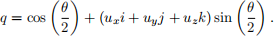
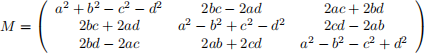
❼ Given a quaternion q = a + bi + cj + dk that represents a rotation, the corresponding rotation
matrix is
❼ Let q1 and q2 be two quaternions that represent rotations. To interpolate from q1 to q2 , calculate
the quaternion

as the parameter t ranges from 0 to 1. When t = 0, the result is q1 ; when t = 1, the result is q2 ; and for 0 < t < 1, the result is a quaternion that is between q1 and q2 , for a geometrically convenient meaning of the word“between”. This calculation involves the following operations.
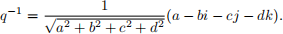
– Given q = a + bi + cj + dk, the inverse q −1 is
– In the special case where q = a + bi + cj + dk is a unit quaternion (which is all you need), qt can be calculated as follows. First write q in the form

where

(This is called polar form.) Then

(5 marks for correct implementation of the math, 3 marks for demo working as described)
5. Tidy Up (5 marks). Reread your code. Imagine the experience of a person who is not you, reading your code. Make that experience better. In particular, the graders will be looking for the following.
❼ In Question 1, you have to set up several different ortho modes. Cut down on repetitive code as
much as you can. Are there certain literals that you use repeatedly? Make them constants with meaningful names.
❼ Make sure that each function is doing its job, and only its job. In the 2D pipeline implementation,
you may find that your problems are easier to solve when you remove extraneous operations from functions like getCamera() and getOrtho().
❼ In Question 4, start from a few high-level functions that carry out the main steps of the demo, and
gradually work down to the lower-level technical details. It is better to have a lot of short functions than a few long functions. Put some thought into how you want to represent a quaternion in code.
2023-03-09