MEC104 Experimental, Computer Skills and Sustainability: MATLAB Assignment
Hello, dear friend, you can consult us at any time if you have any questions, add WeChat: daixieit
MEC104 Experimental, Computer Skills and Sustainability: MATLAB Assignment
Due on Monday, 20th March, 2023, 18:00
Assignment Regulations
⚫ This is an individual assignment. Every student MUST submit one soft copy of the assignment via the Learning Mall before the due date.
⚫ A coversheet can be created in your own way, but the following information MUST be included: student ID number, full name and email address.
⚫ In your answer sheet, all the formula, derivations, completed MATLAB scripts and functions with original highlighted text format in MATLAB editor, computational results in the command window, and plotted figures, should be part of the answers. For each question, you can use screen shots to provide 1) your coding in MATLAB editor, 2) prompts in command window, 3) results in command window, 4) results shown by plots/figures.
⚫ There is no hard requirement on how the answer sheet must be organized. You can organize your report question by question (i.e. give one section for each question). Then, for each section, you can organize it in your own way. However, the contents and information required by each individual question MUST be provided. You may follow a template on the next page to decide what information to be presented for each question.
⚫ You may refer to textbooks and lecture notes to discover approaches to problems, however, the assignment should be your own work.
⚫ Where you do make use of other reference, please cite them in your work. Students are reminded to refer and adhere to plagiarism policy and regulations set by XJTLU. References, in IEEE style can be attached as an appendix.
⚫ Assignments may be accepted up to 5 working days after the deadline has passed; a late penalty of 5% will be applied for each working day late without an extension being granted. Submissions over 5 working days late will not be marked. Emailed submissions will NOT be accepted without exceptional circumstances.
A Suggestion on Information to be Presented for Each Question
For each problem, for example, Problem 4:
1. Equation derivations:
1) What equation do you use in your coding?
2) Also give all the coefficients, and source terms (e.g. external force/voltage), as necessary.
2. What initial conditions, boundary conditions, time periods, domain size, etc., (computational conditions) are used? Provide schematic diagrams as necessary.
3. Main programme:
Provide the coding below, with necessary comments.
4. Functions
1) Give information on what is this function used for, and what equation is solved, related to point 1.
2) Provide the coding below, with necessary comments.
5. Results
1) Present the results required by each question, which can be numbers, data tables, figures, as appropriate.
2) Comments and analysis of the results:
If required by a question, then you need to do this.
If not required, you can still do this if you wish, which is great!
If you think it is necessary to clarify your results and methods used, then please provide your comments.
6. Flow charts of your programme (if applicable).
Problem 1 Matrix Operation (20 Marks)
P1-1 (5 Marks, 1 Mark for each small question)
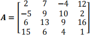
Type this matrix in MATLAB and use MATLAB to carry out the following instructions.
a) Create a vector v consisting of the elements in the third column of A.
b) Create a vector w consisting of the elements in the second row of A.
c) Create a 4 x 3 array B consisting of all elements in the second through fourth columns of A.
d) Create a 3 x 4 array C consisting of all elements in the second through fourth rows of A.
e) Create a 2 x 3 array D consisting of all elements in the first two rows and the last three columns of A.
P 1-2 (5 Marks, 1 Mark for each small question)
Consider the following arrays:
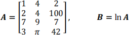
Write MATLAB expressions to do the following.
a) Select just the third row of B.
b) Evaluate the sum of the second row of B.
c) Multiply the second column of B and the first column of A element by element.
d) Evaluate the maximum value in the vector resulting from element-by-element multiplication of the second column of B with the first column of A.
e) Use element-by-element division to divide the first row of A by the first three elements of the third column of B. Evaluate the sum of the elements of the resulting vector.
P 1-3 (5 Marks)
A mass m is suspended by three cables attached at three points B, C, and D, as shown in Figure 1. Let T1, T2, and T3 be the tensions in the three cables AB, AC, and AD, respectively. If the mass m is stationary, the sum of the tension components in the x, in the y, and in the z directions must each be zero. This gives the following three equations:
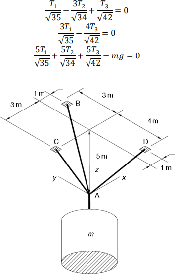
Figure 1. A mass suspended by three cables.
Determine T1, T2, and T3 in terms of an unspecified value of the weight mg. (Hints: you can assume mg = 1, and find the values of T1, T2 and T3, respectively, and the final expressions should be these values multiplied by mg.)
P 1-4 (5 Marks)
Engineers must be able to predict the rate of heat loss through a building wall to determine the heating system requirements. They do this by using the concept of thermal resistance R, which relates the heat flow rate q through a material to the temperature difference ∆T across the material: q = ∆T/R . This relation is like the voltage-current relation for an electric resistor: i = v/R . So, the heat flow rate plays the role ofelectric current, and the temperature difference plays the role ofthe voltage difference. The SI unit for q is the watt (W), which is 1 joule/second (J/s). The wall shown in Figure 2 consists of four layers: an inner layer of plaster/lathe 10 mm thick, a layer of fiber glass insulation 125 mm thick, a layer of wood 60 mm thick, and an outer layer of brick 50 mm thick. If we assume that the inner and outer temperatures Ti and To have remained constant for some time, then the heat energy stored in the layers is constant, and thus the heat flow rate through each layer is the same. Applying conservation of energy gives the following equations.

The thermal resistance of a solid material is given by R = D/k , where D is the material thickness and k is the material’s thermal conductivity. For the given materials, the resistances for a wall area of 1 m2 are R1 = 0.036, R2 = 4.01, R3 = 0.408, and R4 = 0.038 K/W. Suppose that Ti = 20 ℃ and To = −10 ℃ . Find the other three temperatures and the heat loss rate q, in watts. Also, compute the heat loss rate if the wall’s area is 10 m2 .
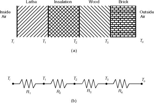
Figure 2. The schematic for P1-4.
Problem 2 (20 Marks)
P2-1 (10 Marks, 7 Marks for programming and 3 Marks for displaying results)
The equation of motion for a pendulum whose base is accelerating horizontally with an acceleration a(t) is
L ![]() + g sin e = a(t) cos e
+ g sin e = a(t) cos e
Suppose that g = 9.81 m/S 2 , L = 1 m, and ė(0) = 0. Plot e(t) for 0 ≤ t ≤ 10 S for the following three cases:
a) The acceleration is constant: a = 5 m/S 2 , and e(0) = 0.5 Tad .
b) The acceleration is constant: a = 5 m/S 2 , and e(0) = 3 Tad .
c) The acceleration is linear with time: a = 0.5t m/S 2 , and e(0) = 3 Tad .
P2-2 (10 Marks, 7 Marks for programming and 3 Marks for displaying results)
The following equation describes the motion of a certain mass connected to a spring, with no friction
3![]() + 75y = f(t)
+ 75y = f(t)
where f(t) is an applied force. Suppose the applied force is sinusoidal with a frequency of 业 Tad/S and an amplitude of 10 N: f(t) = 10 sin(业t).
Suppose that the initial conditions are y(0) = ẏ(0) = 0. Plot y(t) for 0 ≤ t ≤ 20 S . Do this for the following three cases. Compare the results of each case:
a) 业 = 1 Tad/S
b) 业 = 5 Tad/S
c) 业 = 10 Tad/S
Problem 3 (20 Marks, 5 Marks for a) and 15 Marks for b))
The equations for an armature-controlled dc motor (Figure 3) are the following. The Motor’s current is i and its rotational velocity is 业.
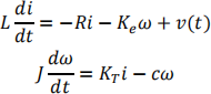
where L, R, and J are the motor’s inductance, resistance, and inertia; KT and Ke are the torque constant and back emf constant; c is a viscous damping constant; and v(t) is the applied voltage.
Use the values R = 0.8 Ω, L = 0.003 H, KT = 0.05 N ∙ m/A, Ke = 0.05 V ∙ s/Tad, C = 0 and J = 8 × 10⁻⁵ kg ∙ m2 .
a) Suppose the applied voltage is 20 V. Plot the motor’s speed and current versus time. Choose the simulation time period large enough to show the motor’s speed becoming constant.
b) Suppose the applied voltage is trapezoidal as given below.
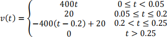
Plot the motor’s speed versus time for 0 ≤ t ≤ 0.3 s. Also plot the applied voltage versus time. How well does the motor speed follow a trapezoidal profile?
For both a) and b), the initial conditions are i(0) = 0 and 业(0) = 0. You can use either MATLAB programming (read Tutorial 1 for solving ODEs) or Simulink (read Lecture 3).
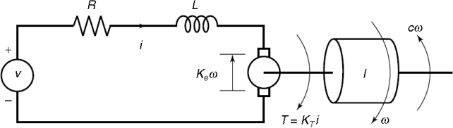
Figure 3. The armature-controlled dc motor of Problem 3.
Problem 4 (25 Marks, with 1) 10 Marks, 2) 15 Marks)
Consider a circuit system as shown in Figure 4.
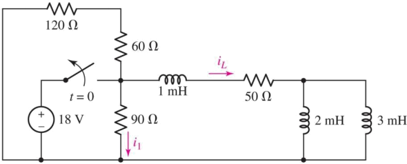
Figure 4. A circuit with multiple resistors and inductors for Problem 4.
Question:
1) Derive the equations for i1 (t) and iL (t) for all t .
2) Obtain the plots of i1 (t) and iL (t) for all t .
Problem 5 (15 Marks, with 1) 5 Marks, 2) 5 Marks, 3) 5 Marks)
A dynamic structure diagram of a control system is shown in Figure 5:
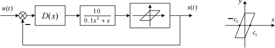
Figure 5. The dynamic control system for Problem 5.
Where
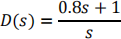
The input is taken as the step input and C is the deadband value of the magnetic loop property.
Question:
1) Use MATLAB/Simulink to establish the system.
2) Analyze the influence of C1 value on the output performance of the system.
3) Analyze the influence of input amplitude on the output performance of the system.
2023-03-07