CIVE50003 Computational Methods II
Hello, dear friend, you can consult us at any time if you have any questions, add WeChat: daixieit
CIVE50003 Computational Methods II
Coursework – Influence lines and bridge structures
This project is to be carried out individually using the Matlab programming environment. Please make an electronic submission on Blackboard of a report (no more than 12 pages in pdf format) and your complete Matlab code (all m files). Your report should include a detailed critique of your findings in the context of finite element and structural theory, including computational considerations where appropriate. Please write carefully and professionally and use appropriate formatting in your document. You may collaborate and use any code released to you, but you may not share any files or results. The deadline is 5 pm on Wednesday 5th April 2023.
You have been asked to investigate the statics of a truss bridge under the action of a moving train locomotive with the aid of influence lines. An influence line tracks the change of a force or moment at a single location depending on how a load pattern moves across the structure. It is an important concept in the study of bridges.
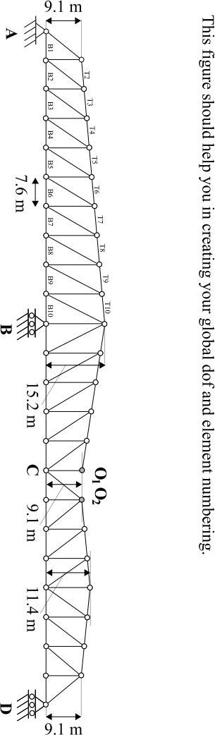
A symmetric truss bridge is illustrated in Fig. 1. It consists of a simply-supported ‘central span’ resting on the tips of two opposing ‘cantilever arms’, which in turn are supported by ‘anchor arms’ . Assume that all members, or ‘chords’, are pin-ended bars carrying only an axial force. Such bridges were commonly built as part of railway networks in the 19th century all over the world (the Forth Railway Bridge in Edinburgh is a famous example), and were often statically determinate to enable a simple analysis of the statics. The action of the locomotive may be represented as a 2 MN point load moving along the bottom line of horizontal chords from A to F.
Assume that each chord is a built-up I-section with dimensions as shown to the right. Assume a modulus of elasticity of 200 GPa and, where applicable, a yield stress of 355 MPa.
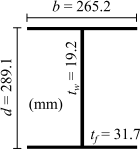
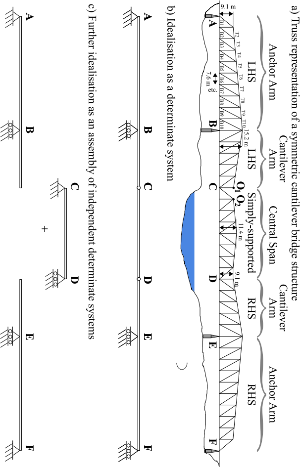
Fig. 1 – Determinate truss steel railway bridge and its various idealisations. The geometry is also given, with each ‘bay ’ having a 7.6 m span.
NOTE: In whatfollows you mayfind it beneficial and intuitive to ‘animate’ the bridge as the locomotive passes over it. The following code snippet can be usefully adapted for this:
figure(‘unit’, normalized’,‘outerposition’,[0 0 1 1]);
% insert intermediate code here
for (each locomotive position)
% insert intermediate code here
clf;
% execute FE plotting code here and a ‘hold on’
drawnow; pause(0.5);
end
Q1. Considering only global static equilibrium and without using finite element analysis yet, draw the influence lines for the vertical reactions at A and B as the locomotive moves from A to F. Draw the influence line for the vertical force that must be resisted by the DEF portion of the bridge when the locomotive is on the ABCD portion of the bridge. Treat this henceforth as a vertical ‘reaction ’ at D.
Q2. With reference to your hand calculations in Q1 and also Fig. 1, explain why a finite element model of the entire structure ABCDEF is not necessary.
Q3. Write a general Matlab Class BRIDGE to represent a finite element model of only the ABCD portion of the bridge, treating the effect of the DEF portion as a horizontal roller support at D (why?). Research Cholesky decomposition (the chol command) and use it in the most efficient way possible in your FE solver, justifying why it can be very beneficial to performance. Show that you are able to obtain the same influence lines for the vertical reactions at A, B and D as in Q1. Comment on how you could, in fact, reduce the size of the finite element model even further.
NOTE: the very general Matlab Class BRIDGE should abstractly represent any possible bridge model you will encounter here. The generic modules for matrix assembly, FE solution, plotting (perhaps with force calculation) should be coded as separate methods of such a Class, in addition to the ‘create instance’ method. Since every truss model will have the same nodes, dofs and element connectivity and will differ only through the locations of the point load representing the moving locomotive, you should have this ‘base arrangement’ come as standard each time you create an instance of the Class and this information should not be present in your main calling program. Neat and elegant code is required, with proper commentary, annotation and indentation (consider using CTR+I to automate this).
Q4. Using both structural and computational arguments, demonstrate why the loss of any diagonal chord is a Bad Thing.
Q5. Add a single horizontal chord at the location identified by O1O2 in Fig. 1. Compare the influence lines for the vertical reactions at A, B and D that you now obtain with those from Q1 and Q3. Comment on the possible reasons for any differences.
NOTE: whether or not to include this chord should be a method of your Class.
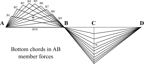
Q6. Remove the additional horizontal chord that you added in Q5. Compute the influence lines for the bottom chords marked B1 to B10 in Fig. 1 and plot these all on the same properly-annotated figure. Which of these chords exhibits the maximum possible axial force and where is the locomotive located when it does so? Do the same anew for the top chords marked T2 to T10 (on their own common figure).
NOTE: use the dofs that you compute by FE for each model to calculate the axial force in each chord of interest via the transformation matrix for a 2D bar element. For the bottom chords, your influence lines should resemble something like this:
Q7. What is the factor of safety of the bridge against a) Euler column buckling and b) plastic collapse and what is the critical chord in AB for both conditions? Comment on whether the top and bottom chords of the anchor arm can safely resist the passing locomotive. Structurally, where is the worst place to put the locomotive?
NOTE: The critical Euler column buckling loadfor pin-ended member of length L is Pcr = EI(π/L)2, where I is the 2nd moment of area in minor-axis bending, while the squash load is Ps = Aσy. The truss chord members are so slender that buckling will probably always control under compression.
Q8 Repeat Q6 and Q7 with the additional horizontal chord at O1O2 . How do the influence lines and factor of safety change?
Q9* (OPTIONAL BONUS). Consider Fig. 2 below, and then watch Buster Keaton over the Easter holidays.
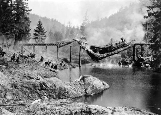
Fig. 2 – A scene from Buster Keaton’s 1926 film The General. Yes, they actually destroyed a train and a bridge in order to film this. It was the most expensive film scene shot during the silent film era.
References
Snyder L.K. (1932) “A study of influence line analysis of stresses in a cantilever style highway bridge” MSc Thesis, School of Mines and Metallurgy, The University of Missouri, USA.
END
AJS Feb’ 23
2023-02-24
Influence lines and bridge structures