MECH0026 – Elasticity and Plasticity
Hello, dear friend, you can consult us at any time if you have any questions, add WeChat: daixieit
MECH0026 – Elasticity and Plasticity
Finite Element Analysis Coursework : Plasticity
1. Introduction
The uniaxial tensile test is one of the most commonly used methods to determine the material’s stress-strain response in both the elastic and plastic phases. It is usually employed for isotropic materials to obtain mechanical properties such as Young’s modulus, yield stress and ultimate tensile strength (UTS). The material properties are then used in the analytical or numerical (FEA) studies to design and analyse mechanical components, and monitor structural integrity. The uniaxial tests are often simulated using FEA to calibrate the material parameters before utilising them for applications. The stress-strain behaviour obtained from the FEA simulation is checked against the experimental data to validate the material model.
In this assignment, the finite element analysis of a tensile test is performed until failure for a dumbbell-shaped specimen by using the material properties obtained from an experiment carried out in the Structures Laboratory at UCL. The results from the FEA are then compared with the experimental data.
2. Assignment Aim
The aims of this assignment are the following:
• To calculate the mechanical properties of the material from the uniaxial tensile test;
• To show how the finite element method can be used to model the elastoplastic response of a ductile material, including yielding, necking, softening and failure;
• To obtain practical experience in using the commercial finite element package ABAQUS for simulating an experiment;
• To demonstrate a critical analysis ofthe output obtained from the finite element analysis calculations, commenting on mesh convergence, element behaviour, and material model;
• To compare the results of the finite element analysis with the experimental data, commenting on their accuracy and the influence of the material model employed in ABAQUS.
3. Uniaxial tensile test on Aluminium thin specimen
A uniaxial tensile test on an Aluminium specimen was performed in the Structures Laboratory at UCL (video 1: force-displacement,video 2: stress-strain). The strain was measured by using the Digital Image Correlation (DIC) method, a non-contact measuring technique to obtain full- field data [1]. The stress was obtained by using the force sensor of the universal testing
machine. Figure 1 shows the Aluminium dumbbell-shaped plate, of 1.5 mm thickness, used for the experiment.
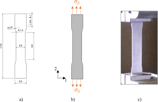
Figure 1: Dumbbell-shaped specimen for the uniaxial tensile test. a) Geometry of the sample, with dimensions in mm; b) Tensile loading of the specimen; c) Picture of the laboratory testing, where the sample is clamped between two grips, and subjected to tensile loading.
The engineering stress-strain curve obtained for the point on the specimen experiencing the maximum longitudinal strain is plotted in Figure 2a. The linear portion of the curve (Figure 2b), representing the elastic phase of the material, can be used to calculate Aluminium Young’s modulus, E. The yield strength, GY , and yield strain, cY , can be obtained through the offset method [2]. The Poisson’s ratio of 0.3 was found from the test. The raw data from the experiment, in terms of stress and strain reported in Figure 2, are given in the ‘Experimental engineering stress-curvefor aluminium.xlsx’ document on the MECH0026 Moodle page.
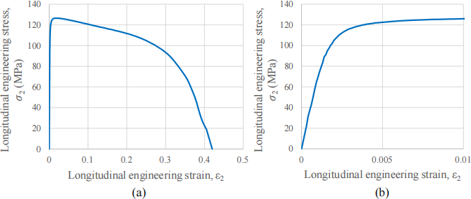
Figure 2: Stress-strain curve from the uniaxial tensile test on Aluminium sheet. (a) Complete stress-strain curve until failure; (b) Zoom-in view of the stress-strain curve until c2 = 0.01.
4. Plastic modelling in FEA
The plastic response of the material can be modelled in FEA by using tabular data in terms of true stress and true plastic strain, beyond yielding. Isotropic hardening model, available in ABAQUS, can be used for this simulation. The relationship between engineering and true measures of stress and strain can be found in the Lecture Handout 4-Fundamentals of Plasticity, or in the lecture notes and weekly videos of topic 4. Further details on implementing plastic material models are given in the ABAQUS documentation [3][4].
5. Damage modelling in FEA
A ductile damage model can be employed to describe the fracture of the Aluminium sample through FEA. It uses the value of plastic strain at necking to determine when to initiate material damage [5, sect. 3.3.1]. After damage initiation, the stress-strain response is governed by the damage evolution law, which is entered in ABAQUS in the form of damage variable, D, as a function of equivalent plastic deformation, ![]() pl . Different damage evolution laws are shown in
pl . Different damage evolution laws are shown in
Figure 3, depicting the accumulated plastic deformation at failure (D = 1) as ![]() f(pl) . Please note
f(pl) . Please note
that the damage process in ABAQUS is mesh dependant. More information on damage modelling is given in the ABAQUS documentation [6].
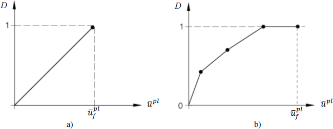
Figure 3: Damage evolution laws to model failure and element deletion in ABAQUS. a) Linear damage evolution law; b) Non-linear damage evolution law through discrete tabular data.
6. Coursework Tasks and Report
Your report should include the following sections:
1. Calculation and definition of the material properties from experimental data (Young’s module, stresses and strains for yield, necking and failure points).
2. Description of the finite element model setup:
• Boundary and loading conditions;
• Element type and its justification;
• Material models employed;
• Mesh configuration used and mesh convergence, including the physical quantity used for monitoring convergence, and the convergence criterion used. NB: Typically, the quantity used for judging convergence is either the quantity of interest, i.e. something that you need to investigate, or a quantity that is most sensitive to mesh density. The convergence criterion is a numerical measurement that shows you how fast you are approaching mesh-independence of results.
3. Post-Processing and examination of results from FEA
• Extraction of the appropriate measure (e.g. engineering, true, longitudinal, equivalent, etc.) of stress and strain at the expected location of failure on the specimen, and a plot of the stress-strain curve. Justify the choice of the stress and strain measures considered.
• Distribution (field output) of the longitudinal strain over the whole specimen for few discrete points, representative of the (i) elastic, (ii) onset of plasticity, (iii) plastic hardening, (iv) necking and (v) softening phases.
4. A discussion on:
• The comparison of the stress-strain data extracted from FEA with the experimental measurements, both in the elastic and plastic phases (e.g. by reporting on the same plot the experimental and numerical stress-strain curves, by quantifying the discrepancies between the two results and commenting them);
• The material models (elastic, plastic, damage) used and how it affects the accuracy of FEA results;
• The location of failure initiation and failure propagation.
7. Due Date and Length of Report
The report is individual. It shall be submitted on Moodle by 3rd March 2023 at 2.00 pm. The main body of the report (excluding title page, table of contents, references) shall not exceed 2000 words. There is no need to use appendices in this report.
8. Marking Scheme
See the accompanying grading rubric.
References
[1] https://www.correlatedsolutions.com/digital-image-correlation/
[2] ASTM International. E8/E8M-16ae1 Standard Test Methodsfor Tension Testing of
Metallic Materials. West Conshohocken, PA; ASTM International, 2016. DOI:
https://doi.org/10.1520/E0008_E0008M-16AE01
[3] Classical metal plasticity:https://abaqus-
docs.mit.edu/2017/English/SIMACAEMATRefMap/simamat-c-metalplastic.htm [4] Defining plasticity in Abaqus:https://abaqus-
docs.mit.edu/2017/English/SIMACAEGSARefMap/simagsa-c-matdefining.htm
[5] M. Pavlović, Z. Marković, M. Veljković and D. Buđevac. Bolted shear connectors vs. headed studs behaviour in push-out tests. Journal of Constructional Steel Research, 88:134- 149, 2013. DOI:https://doi.org/10.1016/j.jcsr.2013.05.003
[6] Damage evolution and element removal for ductile metals:https://abaqus-
docs.mit.edu/2017/English/SIMACAEMATRefMap/simamat-c-
2023-02-23
Finite Element Analysis Coursework: Plasticity