Fault Detection, Isolation and Recovery
Hello, dear friend, you can consult us at any time if you have any questions, add WeChat: daixieit
Fault Detection, Isolation and Recovery
Assignment: Fault Detection, Isolation & Recovery System for the Heading Motion of a Fixed Wing UAV
Introduction
Fault tolerance is very important for aircraft flight control, particular when the aircraft is an unmanned drone. The majority of the faults occur in the sensors and actuators onboard the aircraft. Once a fault has occurred the aircraft could become uncontrollable and be dangerous to passengers and crew. This assignment is to examine the effects of sensor and actuator faults on the lateral dynamics of a fixed wing Unmanned Aerial Vehicle (UAV).
Background
Lateral Dynamics
The Lateral Dynamics of any aircraft are defined in terms of the Body-fixed velocities and corresponding Earth-fixed orientation (see Figure 1).
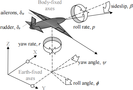
Figure 1: Lateral Flight Dynamics
In this particular case the Body-fixed velocities are roll rate (p) and yaw rate (r). All other Body- fixed dynamics are regarded as constant (e.g. surge velocity) or zero (e.g. pitch). The effects of these velocities on the inertially fixed Earth-fixed axes are represented by the orientation of the aircraft relative to this reference frame. These are the roll angle (0) and yaw angle (v). In addition, the influence of sideslip on the aircraft is included in the form of the sideslip angle (![]() ).
).
The corresponding inputs to the lateral dynamics of the aircraft are the aileron actuator deflection (![]() a) and the rudder actuator deflection (
a) and the rudder actuator deflection (![]() r). The ailerons control the roll motion and the rudder controls the heading or yaw. The Lateral Dynamics of an UAV can be represented by the following differential equations:
r). The ailerons control the roll motion and the rudder controls the heading or yaw. The Lateral Dynamics of an UAV can be represented by the following differential equations:
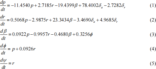
Here the translational velocities are measured in m/s, rotational velocities in rad/s and the angles in radians. The longitudinal velocity of the UAV is taken to be U0 = 30 m/s at an altitude of 500m above sea level.
In addition to the flight dynamics, this aircraft representation also includes the dynamics of the aileron and rudder actuators. Both actuators have a maximum amplitude deflection of ±75° and a maximum rate limit of ±20°/s.
Control of the UAV
This UAV has 2 modes of operation i.e. remote open loop control and closed loopflight control. The remote open loop control takes aileron and rudder commands from a ground based operator and directly applies them to change the motion of the UAV. The closed loop flight control uses a feedback control system to make the UAV follow manoeuvring commands from the operator e.g. heading angle change commands. Both of these conditions shall be considered in this study.
Faults in Lateral Dynamics
The faults in the Lateral Dynamics of an aircraft can be either multiplicative or additive. The multiplicative faults occur within the dynamics of the aircraft and can be caused by changes to the aircraft itself during flight.
Additive faults caused by the sensors and actuators in the system are the main focus of this assignment. In particular faults that occur on the heading (yaw) channel that are added to the measured dynamics from the aircraft sensors and to the rudder input actuator.
Assignment Specification
This assignment involves the development and analysis of Fault Detection, Isolation and Recovery (FDIR) Systems for the Lateral Dynamics of the UAV described above. The assignment activities are based on the development of 2 separate FDIR systems:
. The “Open-Loop” FDIR System will involve the construction of a continuous time simulation of the UAV and its remote “Open-Loop” control by a ground based operator. Faults will be introduced to the rudder actuator and heading sensor output for the UAV’s heading channel. The purpose of the FDIR system is to detect, isolate and determine suitable recovery options for this “Open-Loop” operation of the UAV.
. The Closed-Loop FDIR System will involve the design of a control system for the heading (yawing) motion of the UAV. This control system will provide control signals for the rudder actuator, which in turn regulates the heading motion of the UAV. Faults will be introduced to the rudder actuator and heading sensor output for the UAV’s heading channel. The purpose of the FDIR system is to detect, isolate and determine suitable recovery options for this Closed-Loop operation of the UAV.
In order to fulfil the requirements for this assignment you should complete the following tasks:
“Open-Loop” Operations
1. Construct a continuous time simulation of the Lateral Dynamics of the UAV using zero initial conditions i.e. assuming UAV is flying level with initial heading of zero.
2. (a) Simulate a 10°/- 10° zig-zag heading manoeuvre where changes in heading can be
observed. A zig-zag heading manoeuvre involves setting the rudder to ±20° and waiting until the heading reaches ±10° . Then the polarity of the rudder deflection is reversed and the process is repeated in the negative sense.
(b) Investigate the effect of separate simulated stepwise and driftwise faults applied to
the sensor in the heading channel during a 10°/- 10° zig-zag manoeuvre.
(c) Investigate the effect of separate simulated stepwise and driftwise faults applied to the rudder actuator in the heading channel during a 10°/- 10° zig-zag manoeuvre.
(d) Employ suitable fault detection and isolation mechanisms to determine when and where these faults occur during the “Open-Loop” 10°/- 10° zig-zag manoeuvre.
(e) Employ suitable recovery procedures that will enable the “Open-Loop” Operation
to continue in the presence of sensor and actuator faults.
(f) Investigate the operation of the FDIR system you have developed with simulated
white noise of amplitude ±20° included in the heading output.
Closed-Loop Operations
3. (a) After completing the “Open-Loop” Operations stage above, remove the faults from
your simulation and design a closed-loop heading flight controller for this UAV that can perform a 60° controlled heading manoeuvre by manipulating the rudder deflection.
(b) Investigate the effect of separate simulated stepwise and driftwise faults applied to
the sensor in the heading channel during a 60° controlled heading manoeuvre.
(c) Investigate the effect of separate simulated stepwise and driftwise faults applied to the rudder actuator in the heading channel during a 60° controlled heading manoeuvre.
(d) Employ suitable fault detection and isolation mechanisms to determine when and where these sensor and actuator faults occur during the closed-loop 60° heading manoeuvre.
(e) Employ suitable recovery procedures that will enable the Closed-Loop Operation
to continue in the presence of sensor and actuator faults.
(f) Investigate the operation of the FDIR system you have developed with simulated
white noise of amplitude ±20° included in the heading output.
Assignment Deliverable – Assessment Document
Write a technical report outlining your investigation of how the faults affect this system and how your FDIR systems addressed the tasks outlined in Assignment Specifications above. This will be used to assess your work for this course assignment. The submission time/date for this assignment report is 4:30pm on 19th April 2023 via the moodle page for this course.
2023-02-19
Fault Detection, Isolation & Recovery System for the Heading Motion of a Fixed Wing UAV