Parallel Design Patterns Assessed Coursework, 2023 PART ONE
Hello, dear friend, you can consult us at any time if you have any questions, add WeChat: daixieit
Parallel Design Patterns
Assessed Coursework, 2023
PART ONE
About the coursework
The assessment for Parallel Design Patterns is split into two parts. This first submission (“part one”) comprises of a short report. I expect that a complete answer could be expressed succinctly in three or four pages. The second submission (“part two”) builds on this same problem.
Overview of the problem
You will solve a problem similar to one often faced by developers working at EPCC. As society continues to embrace non-carbon based energy sources, the use of small modular nuclear reactors (SMR) is one possible solution. As such, nuclear engineers would like to further understand not only the properties of this new type of reactor but also existing reactor types in the current fleet. To this end they have developed a simulation code which allows them to model nuclear fission within a reactor core.
A more detailed description of the model is provided later in this document.
Your tasks
For this, coursework part one, you should analyse the problem and write a report answering the following key questions:
1. [weighting: 60%]
a. Select two patterns from the parallel algorithm structure/strategy design space that you believe could be used for this problem. For both patterns discuss how the pattern’s context and forces relate to the problem, the advantages and disadvantages of your choice of pattern, and why you consider it suitable.
b. From the two patterns you have described in part a, which one would you select for this problem and why?
c. Given the pattern you have selected in part b, what aspects of the pattern and its solutions might be relevant to the choice of implementation language or hardware platform?
d. Given the pattern selected in part b, what aspects of your design might ultimately limit the overall parallel performance and scaling achieved when it is implemented, and what trade-offs might need to be considered to address these?
2. [weighting: 25%]
a. Select two patterns from the parallel algorithm structure/strategy design space that you think are inappropriate for this problem, for both patterns describe the disadvantages of the pattern in relation to this problem and why it would not be a suitable choice here.
3. [weighting: 15%]
a. Based on the problem described in this handout, what approach(es) might you use to help evaluate the nuclear engineer’s existing serial code?
b. What techniques would be useful in measuring the performance and scaling of your parallel design and code as it develops?
Details of the nuclear engineer’s reactor core model
The model that the nuclear engineers have written exhibits the following behaviour:
• The reactor core is represented as a cube in three dimensions and consists of numerous two-dimensional channels which are cuboid.
o These channels run all the way down the reactor in the vertical (z) dimension and in the x and y dimensions are 20 cm. Channels are placed next to each other, so for instance in a reactor core of 1m3 there will be five rows of five channels, each 1 metre deep in vertical length.
o Channels can contain nothing (they are empty), nuclear fuel assembly, control rod, a moderator, or a neutron generator. It is only possible for each individual channel to contain one of these.
o A fuel assembly is made up of fuel pellets. Each pellet is x=40mm by y=40mm by z=2mm and weighs 1 gram. Fuel pellets are stacked on top of each other all the way down the fuel assembly channel.
• The simulation progresses in timesteps, where a timestep is measured in nano seconds (which is 1e-9 seconds).
o The size of each timestep (in ns) is configurable as an input parameter.
• The simulation also contains lots of neutrons which are free to pass through the reactor core and are tracked. At every timestep, the code calculates the movement of each neutron and updates its position.
o Once a neutron travels outside the reactor core it is deactivated and disappears from the simulation.
• At every timestep, for each neutron, the code will check whether it has interacted with the contents of the reactor core.
o If a neutron enters a fuel assembly channel, then the neutron’s absorption cross section is calculated which is determined by the neutron’s energy and the type of fuel in the reactor.
▪ This cross section is then used to calculate the probability that the neutron has been absorbed by the fuel which also depends on the current number of atoms of that fuel in the pellet. If the neutron is absorbed, then the atom of fuel that it has been absorbed by gains an extra neutron (e.g., goes from U235 to U236) and the neutron disappears from the simulation.
o If the neutron enters the moderator, then the neutron’s scattering cross section is calculated and absorption probability.
▪ Based on these, if the neutron collides with the moderator’s atoms, then it is slowed down (slower neutrons are more likely to cause fission). If the neutron is absorbed by the moderator, then it disappears from the simulation.
o If the neutron enters the control rod channel, then the code calculates whether the neutron has collided with the control rod.
▪ Control rods can be lowered a certain amount into the reactor, so whether the neutron hits the control rod is based upon how far the rod has been lowered and the location of the neutron.
▪ Any neutron-control rod collision results in absorption and the neutron disappears from the simulation.
• At each timestep the state of the reactor core is updated
o All atoms of U236 and Pu240 fission, each fission releases 200MeV of energy
▪ There is an 85% chance that U236 splits into Barium and Krypton which releases 3 neutrons. Otherwise, it will split into Xenon and Strontium, releasing 2 neutrons.
▪ There is a 73% chance Pu240 splits into Xenon and Zirconium releasing 3 neutrons. Otherwise, it will release a neutron and mutate into Pu239.
▪ The ejected neutrons’ energy (between 0 and 20 MeV) and resulting velocity components in the x, y and z dimensions is random.
o Neutron generators contain Californium-252 and this will release 23e12 neutrons per gram per second.
▪ Every cm in height of the neutron generator is half a gram in weight.
▪ Again, the resulting neutrons’ energy (between 0 and 20 MeV) and velocity components in the x, y and z dimensions is random.
• The size and configuration of the reactor core (e.g., the type of each channel) is provided by the user via a configuration script.
o Reactor fuel can be a mixture of U235, U238, Pu239 and the configuration script provides the percentage of these in fuel assemblies.
▪ Only U235 and Pu239 will fission, U238 does not.
▪ From these percentages the code calculates the number of atoms in each fuel pellet for each chemical, with other elements that are fission by- products (Barium, Krypton, Xenon, Strontium and Zirconium) set to zero initially.
o The moderator can be one of water, heavy water (deuterium) or graphite. Each has different neutron slowing and absorption properties. The weight of the moderator in each channel is provided in grams.
▪ For instance, water is more likely to slow neutrons but also much more likely to absorb them.
▪ We want the moderator to slow down the neutrons to increase the probability of fission, but we do not want it to absorb neutrons.
▪ The heavier the moderator then the more of it is present, this will raise the probability of neutron slowing and moderator absorption.
o The percentage of how far each control rod has been inserted into the reactor core can be provided, and if this is omitted then it is assumed a zero value (i.e. the control rod is fully out of the reactor).
• Due to limitations of the simulation (runtime and memory), the engineers have set a maximum number of neutrons that can be active at any one time.
o This artificial limit impacts the ability for the simulation to undertake fusion, and-so they have also introduced an artificial absorption probability multiplier, which increases the probability that an individual neutron is absorbed by the fuel by a specific multiplication factor.
o Ideally, the parallelisation of their code will mean that they can remove these approximations.
• Periodically the state of the reactor should be appended to a file.
o This should contain, the simulation time, amount of energy released via fission and for each fuel assembly the number of atoms of Uranium (235, 236 and 238), Plutonium (239 and 240), Barium, Krypton, Xenon (134 and 140), Strontium and Zirconium present.
o The frequency of this reactor state storage is configurable by the user.
• There should be frequent summaries of simulation progress printed to stdio
o Which includes the current simulation time, the number of active neutrons, the number of fissions so far and total amount of energy released through fission.
• The simulation will terminate when a predetermined number of timesteps is reached.
o A short report is printed to stdio which reports the total number of fissions that have completed and associated energy release, along with the simulation code’s runtime.
Parameters
The nuclear engineers have provided several configurations of the reactor core simulation to you, an example simulation configuration is described here (this is intended to give you an idea of the state of their current code which they wish to accelerate). Their serial code running on a single CPU core of Cirrus currently takes 82 minutes and 20 seconds to run this configuration which models 1e-4 seconds of simulation time.
• Reactor size: x=1m, y=1m, z=1m
• Maximum number of neutrons: 10000000
• Number of timesteps: 10000
• Size of each timestep (in nano seconds): 10
• Fuel: 15% U235 and 85% U238
• Moderator: Water and weighs 1000000 grams per channel
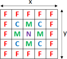
The diagram below illustrates the layout of the reactor’s channels in this configuration (viewing from the top, a bird’s eye view of the reactor core.) Where F is a fuel assembly channel, C is a control rod channel, M is a moderator channel and N is a neutron generator.
As can be seen from this information, a configuration such as this contains a limited maximum number of neutrons in the simulation and the nuclear engineers would like to have a parallel code that enables them to include many more of these, as well as study larger reactors with more complex configurations over a longer amount of simulation time.
2023-02-03