COM00011C System and Devices 1
COM00011C
DEPARTMENT OF COMPUTER SCIENCE
System and Devices 1
SYS1 Open Assessment 2020/21
This assessment continues the work started in practical 9. When answering these questions you must use the assembler and ISE project files from the Exam folder on the VLE.
The bug trap's functionality and accuracy are to be further improved by the addition of a camera. To implement the required bug detection algorithms a number of new software routines are required. Your task is to implement these functions. Where required new instructions and additional hardware may be added to improve processing performance. However, to ensure compatibility with other systems the following restrictions are imposed:
• The maximum clock speed used by the system is limited to 10MHz.
• Instruction names and machine code implementations i.e. bit fields used, are restricted to those defined in Appendix A.
• The assembler simpleCPUv1d_as.py may not be modified.
• Only a single macro file : simpleCPUv1d.m4 may be used.
• The following ISE files may not be altered:
◦ CPU test-bench – cpu_tb.vhd
◦ Computer schematic – computer.sch
◦ Processor schematic – simple_cpu_v1d.sch
◦ Memory model – ram_4Kx16_sim_v1a.vhd
• Input images are limited to the file : bug24×24.ppm which can be downloaded from the Exam folder on the VLE.
• Output images are limited to 24×24 pixels in size and must use the PPM or PGM image formats, as defined in each question.
The component symbols used in the schematic simple_cpu_v1d may not be altered e.g. DATA_MUX, COUNTER_12, ALU, REGISTER_FILE_4 etc. However, the hardware within these components can be modified e.g. you can not alter the ALU symbol, but you can add additional processing elements to the ALU schematic.
Note, if the external interfaces of these components are altered you will be awarded a zero mark for the questions affected.
You may implement any of the instructions defined in Appendix A. However, you do not need to do so to complete the programming tasks in questions 2,3 or 4. There are also two undefined instructions XOP1 (immediate) and XOP2 (register). You are free to modify the ALU and DECODER to implement new functionality for these undefined instructions. This functionality may be changed to suit the processing requirements of each question. The assembler simpleCPUv1d_as.py has already been updated to support these new instructions and may not be altered.
At the end of each question there is a description of the files that you need to submit. These files should be placed in a directory of the same name i.e. Q1, Q2, Q3, or Q4. When complete these directories should be compressed into a single file: SYS1.zip and uploaded through the submission system.
Q1 (10 marks)
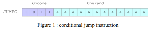
To detect overflows during unsigned additions a new conditional jump instruction is required. This instruction should use the instruction format shown in figure 1. If the carry flag in the status register is set the processor should jump to the absolute address specified in the instruction, otherwise the program counter should be incremented to the address of the next instruction.
Modify the file decoder.vhd to implement this new instruction. This file will be added to the base ISE project and tested using the test code shown in Appendix A. The assembler simpleCPUv1d_as.py has already been updated to support this new instruction.
Write out the RTL descriptions of the micro-instructions used to perform this instruction during the Fetch, Decode and Execute phases, and briefly describe what signals are used and the modifications made to the file decoder.vhd. These descriptions must be submitted as a plain text file named: jumpc.txt.
Submission: for this question you should submit two files : decoder.vhd and jumpc.txt. Do not submit the full ISE project. Files that do not comply to the stated file formats will be awarded a zero mark.
Q2 (10 marks)
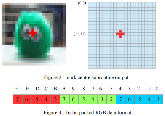
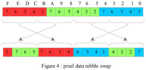
Mark centre : write a program to place a red cross in the middle of an RGB image stored in memory, as shown in figure 2. The centre of the image is define as co-ordinate position (11,11). This image is stored in memory using the packed RGB data type shown in figure 3. For more information on this data type refer to practical 9. This program must be named : markCentre.asm and submitted as a plain text file.
The memory model ram_4Kx16_sim has already been configured to automatically load the tested image: bug24x24.ppm and store it at base address 1024. When your program has finished processing this image it must store the value 0x00 to address 0xFFF to trigger the generation of the output image file: output.ppm.
Your program must be capable of processing an image in 2.5 us, programs not meeting this minimum requirement will be awarded a zero mark.
Submission: for this question you should submit:
• markCentre.asm : a plain text file, assembly language program used to implement the mark centre functionality. You may also submit a single macro file : simpleCPUv1d.m4 if used.
• Any ISE schematics (.sch files) that have been modified to implement this system.
• Any new ISE schematics (.sch files) and symbols (.sym files) that have been created to implement this system.
Note, remember you are not allowed to modify the top level schematics, as defined on page 2.
These files will be added to the base ISE project from the Exam folder on the VLE for testing. Do not submit the full ISE project. The output image will be regenerate during the marking process. Files that do not comply to the stated file formats will be awarded a zero mark.
Q3(40 marks)
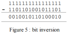
Encrypt : write a program to encrypt RGB image data using a simple block cipher. Encryption is performed on each pixel in two steps. First swap the nibbles in the high and low bytes as shown in figure 4.
Next, each bit position is inverted by subtracting the swapped data from 0xFFFF, as shown in the example in figure 5. The resulting encrypted data is then written to memory.
This program must be named: encrypt.asm and submitted as a plain text file. Again, the memory model ram_4Kx16_sim has already been configured to automatically load the tested image: bug24x24.ppm and store it at base address 1024. When your program has finished processing this image it must store the value 0x00 to address 0xFFF to trigger the generation of the output image file: output.ppm.
To test if your encryption program has worked correctly the python program decrypt.py can be downloaded from the VLE. This will decrypt the encrypted PPM image output.ppm to produce a new file call new.ppm.
Your program must be capable of processing an image in 15 ms, programs not meeting this minimum requirement will be awarded a zero mark. Full marks will only be awarded if the program is capable of processing an image in less than 1.22 ms.
The maximum execution time can be achieved using software only solutions. To achieve higher processing speeds new instructions and supporting hardware components will need to be added to the processor, as outlined in practical 9.
Note, these instructions must comply to the restrictions outlined on page 2.
Submission: for this question you should submit:
• encrypt.asm : a plain text file, assembly language program used to implement the encryption functionality. You may also submit a single macro file : simpleCPUv1d.m4 if used.
• Any ISE schematics (.sch files) that have been modified to implement this system.
• Any new ISE schematics (.sch files) and symbols (.sym files) that have been created to implement this system.
Note, remember you are not allowed to modify the top level schematics, as defined on page 2.
These files will be added to the base ISE project from the Exam folder on the VLE for testing. Do not submit the full ISE project. The output image will be regenerate during the marking process. Files that do not comply to the stated file formats will be awarded a zero mark.
The awarded mark for this question is determined by a solution's functionality and processing performance i.e. the mark will be inversely proportional to execution time, ranging from 20 marks for solutions meeting the maximum timing requirements, to 40 marks for solutions matching or exceeding the minimum timing requirements.
Q4 (40 marks)
image = [ ]
new = [ ]
j = 1024
FOR i IN RANGE 1600 to (1600+288)
LOOP
new[i] = Y(image[j+1])<<8 || Y(image[j])
j = j + 2
END LOOP
save( new )
Figure 6 : pseudo code
Generate PGM : write a program to implement the pseudo code shown in figure 6. An initial solution to this problem is discussed on :
http://simplecpudesign.com/simple_cpu_v1d_image/index.html
You are required to optimise this solution’s processing performance and modify its implementation to meet the restrictions stated on page 2.
This code converts RGB image data stored in memory into a grayscale image i.e. the function Y( ). Each new pixel value is represented as an unsigned 8-bit value. Two pixels are packed into each memory location using “little-endian” format i.e. the first pixel is stored in the lower byte position. The grayscale image must be stored in memory at base address 1600.
The brightness of each pixel should be calculated using the perceived brightness (Y) equation :
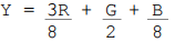
You may use different algorithms to calculate brightness, however, the brightness of each pixel must be within +/- 10% of the reference image output.pgm. This image can be downloaded from the VLE. The output image must use the PGM image format. Solutions not meeting these requirements will be awarded a zero mark.
This program must be named: grayscale.asm and submitted as a plain text file. Again, the memory model ram_4Kx16_sim has already been configured to automatically load the tested image: bug24x24.ppm and store it at base address 1024. When your program has finished processing this image it must store the value 0x00 to address 0xFFF to trigger the generation of the output image file: output.pgm.
Note, as previously specified the grayscale image must be stored at base address 1600, with two pixel values stored in each memory location.
Your program must be capable of processing an image in 225 ms, programs not meeting this minimum requirement will be awarded a zero mark. Full marks will only be awarded if the program is capable of processing an image in less than 1.82 ms.
The maximum execution time can be achieved using software only solutions. To achieve higher processing speeds new instructions and supporting hardware components will need to be added to the processor, as outlined in practical 9.
Note, these instructions must comply to the restrictions outlined on page 2.
Submission: for this question you should submit:
• grayscale.asm : a plain text file, assembly language program used to implement the grayscale functionality. You may also submit a single macro file : simpleCPUv1d.m4 if used.
• Any ISE schematics (.sch files) that have been modified to implement this system.
• Any new ISE schematics (.sch files) and symbols (.sym files) that have been created to implement this system.
Note, remember you are not allowed to modify the top level schematics, as defined on page 2.
These files will be added to the base ISE project from the Exam folder on the VLE for testing. Do not submit the full ISE project. The output image will be regenerate during the marking process. Files that do not comply to the stated file formats will be awarded a zero mark.
The awarded mark for this question is determined by a solution's functionality and processing performance i.e. the mark will be inversely proportional to execution time, ranging from 5 marks for solutions meeting the maximum timing requirements, to 40 marks for solutions matching or exceeding the minimum timing requirements.
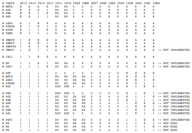
Appendix A : SimpleCPUv1d instruction-set
Appendix B : JUMPC test code
start:
move ra 0xff # load register ra 0xFFFF
jumpc fail # carry flag not set, no jump
add ra 0x1 # add 1 to generate carry
jumpc pass1 # carry flag set, jump
fail:
jump fail # fail, trap
pass1:
add ra 0x1 # add 1 no carry generated
jumpc fail # carry flag not set, no jump
pass2:
jump pass2 # pass, trap
2021-05-04