MECH5900M Term Project 2021
MECH5900M Term Project 2021
Jongrae Kim
University of Leeds, Leeds, UK
Term Project Guideline
• Each task must be thoroughly discussed. No discussion would cause sig-nificant deduction in the marks.
• You are not allowed to share or discuss the term project with anyone.
• Total mark of the term project is 100%, which is 50% of the total module mark.
• Submission link will be appeared in the minerva module website and you will be notified by email when the link is activated.
• Report format to be submitted is in pdf; Use pdf generation function in ms-word or print it in file with pdf format.
• In the report, use 11pt font size and single line space. For each task, the length of the pages is less than 5 pages.
• Report submission due is 12pm, Noon, Thursday 6th May 2021
• Include all matlab m-scripts and simulink blocks used in the report in appendix. Appendix is not included in the page limitation.
• Questions for the term project would be answered only if the questions are to clarify the tasks. The questions about how to do it won’t be answered.
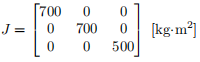
Task 1 Spin-Up Manoeuvre with Ideal Actuator [25%]
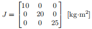
The moment of inertia of the spin-stabilized satellite is given by
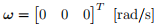
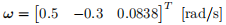
The initial angular velocity is by
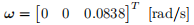
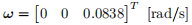
and the desired angular velocity is given by
Assume that the satellite is equipped with the ideal actuator, which can produce any desired torque. Note that the magnitude of torque must be small than 2Nm.
• Derive the LQR (Linear Quadratic Regulator) controller for spin-up ma-noeuvre. Show all steps of the derivations. [10%]
• Implement the LQR controller in Simulink with the full nonlinear quater-nion and rotational dynamics. Justify your choice of the weighting matri-ces, R and Q, in the LQR controller, where ”justify” means that the design parameter choice must be supported by computer simulations. [10%]
• Show the time history of angular velocity and of the control torque. [5%]
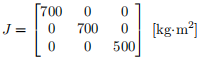
Task 2 Active Nutation with Gas Thruster [25%]
The moment of inertia of the spin-stabilized satellite is given by
and the initial angular velocity is by
The desired angular velocity is given by
The satellite is equipped with gas thrusters for each axis, where the torque is either +2 or -2 Nm for each body axis. For x and y body axes, it can be written in the following state-space form:

• Define A, B, x and u for the active nutation damping control. For LQR Control Design, the controllability matrix, C, must be the full-rank, where
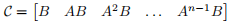
and n is the dimension of A, i.e., A is an n × n matrix. Construct C and calculate the rank using rank function in MATLAB. [5%]
• Design the active nutation control using LQR (Linear Quadratic Regula-tor) control algorithm, and justify the choice of Q and R in the LQR de-sign, where ”justify” means that the design parameter choice must be sup-ported by computer simulations and/or mathematical derivations. [8%]
• Design PWM (Pulse-Width Modulation), i.e., the Schmitt Trigger, for LQR command to use Gas Thruster, and justify the choice of on/off values for PWM switching, where ”justify” means that the design parameter choice must be supported by computer simulations. [8%]
• Show the time history of the angular velocity. [2%]
• Show the time history of the thruster firing for each axis. [2%]
Task 3 Quaternion Feedback Control: Reaction Wheel [25%]
The moment of inertia of the 3-axis stabilized satellite is given by
and the initial quaternion and angular velocity at t = 0 are given by
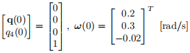
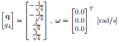
The desired attitude is given by
The satellite is equipped with three reaction wheels and each wheel generates torque for each body-axis. The three reaction wheels are identical and their characteristic are as follows: Jwheel = 0.5 [kg·m2 ] and the initial angular velocity of all reaction wheels relative to the satellite is zero.
• Using the following quaternion feedback controller:
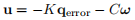
where qerror is the error quaternion to be appropriately defined between the current quaternion and the desired quaternion,
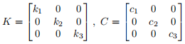
Determine the control gains, K and C, and justify the choice of the gains, where ”justify” means that the design parameter choice must be supported by computer simulations and/or mathematical derivations. [15%]
• Show the time history of the quaternion. [5%]
• Show the time history of the control input torque by the reaction wheel and the time histories of the three reaction wheels angular velocities. [5%]
Task 4 Robustness Analysis [25%]
The quaternion feedback controller designed in Task 3 is to be tested for its robustness with respect to the uncertainties in the moment of inertia, J. The true J is now perturbed as follows:
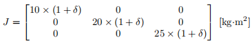
All the other simulation parameters including the quaternion feedback control gains, the initial quaternion and the initial angular velocities remain the same as ones in Task 3.
• Let the uncertainty be in the range of −0.1 ≤ δ ≤ 0.1. For the different δ values, calculate the settling time, ts, through computer simulations. The settling time is defined by

and draw the plot ts with respect to δ. [15%]
• Discuss the limitations of the uncertainty, δ, introduced in the moment of inertia in the task and suggest more realistic uncertainties in the moment of inertia. [10%]
END.
2021-04-27